


12.4 PLC Side Setting
12 - 57
CC-Link
C
O
NN
ECTION (INTELLIGE
NT DEVICE ST
A
T
ION)
12
■3.
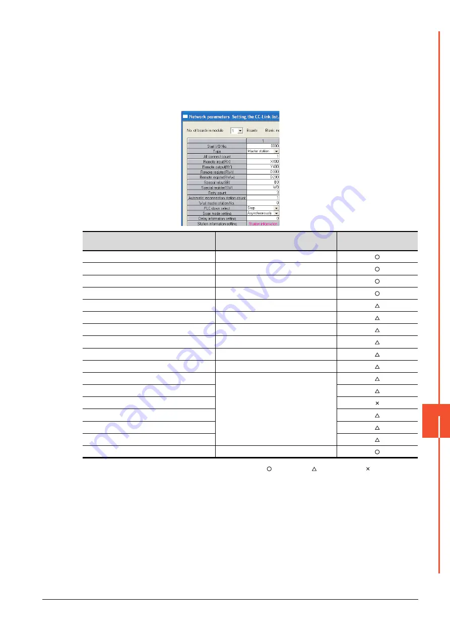
Parameter setting
There are two methods for the parameter setting: perform the setting from [Network parameter] of GX Developer and
the sequence program.
Performing it from the [Network parameter] of the GX Developer can be set only when the PLC CPU and the CC-Link
module use the function version B or later.
(1) Setting from [Network parameter] of GX Developer
(a)
Network parameter
: Necessary : As necessary : Not necessary
Item
Set value
Setting necessity at GOT
connection
No. of boards in module
1
Start I/O No.
0000H
Type
Master station (fixed)
All connect count
1
Remote input (RX)
X400
Remote output (RY)
Y400
Remote register (RWr)
D300
Remote register (RWw)
D200
Special relay (SB)
B0
Special register (SW)
W0
Retry count
(Use default value)
Automatic reconnection station count
Wait master station No.
PLC down select
Scan mode setting
Delay information setting
Station information setting
Refer to (2)
Summary of Contents for GOT2000 Series
Page 2: ......
Page 84: ......
Page 432: ...6 58 6 6 Precautions ...
Page 578: ...9 54 9 6 Precautions ...
Page 726: ...12 84 12 5 Precautions ...
Page 756: ......
Page 822: ...14 66 14 4 Device Range that Can Be Set ...
Page 918: ...15 96 15 7 Precautions ...
Page 930: ...16 12 16 6 Precautions ...
Page 964: ......
Page 1002: ...19 38 19 7 Precautions ...
Page 1022: ...20 20 20 5 Precautions ...
Page 1023: ...MULTI CHANNEL FUNCTION 21 MULTI CHANNEL FUNCTION 21 1 ...
Page 1024: ......
Page 1054: ...21 30 21 5 Multi channel Function Check Sheet ...
Page 1055: ...FA TRANSPARENT FUNCTION 22 FA TRANSPARENT FUNCTION 22 1 ...
Page 1056: ......
Page 1223: ......


