12 - 76
12.4 PLC Side Setting
POINT
POINT
POINT
When changing the sequence program
After writing the sequence program to the PLC CPU, operate the PLC CPU ether turning OFF
and then ON or resetting.
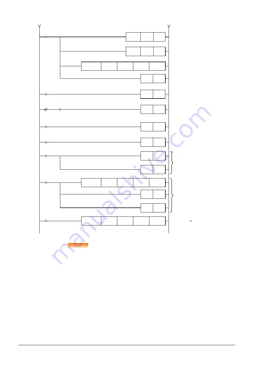
M8002
Unit error
M20
M35
Initial pulse
Unit ready
M3
When data link
startup by buffer
memory parameters
is completed
abnormally
Refresh command
M2
When data link
startup by buffer
memory parameters
is completed normally
M26
M27
M8000
RUN
monitor
M55 to M40 BFM#10
M1
FNC 78
TO
K0
K32
D20
K2
M1
RST
M40
SET
M2
PLS
M3
SET
M46
SET
M46
RST
M3
RST
FNC 79
FROM
K0
H0668
D50
K1
M46
RST
M3
RST
FNC 78
TO
K0
K10
K4M40
K1
FNC 12
MOV
D20
H2301
D21
FNC 12
MOV
HC104
Station information(1st unit)
Ver. 1 compatible intelligent
device station (GOT)
Station information(2nd unit)
Ver. 2 compatible intelligent
device station (GOT)
Station information
From the previous page
Summary of Contents for GOT2000 Series
Page 2: ......
Page 84: ......
Page 432: ...6 58 6 6 Precautions ...
Page 578: ...9 54 9 6 Precautions ...
Page 726: ...12 84 12 5 Precautions ...
Page 756: ......
Page 822: ...14 66 14 4 Device Range that Can Be Set ...
Page 918: ...15 96 15 7 Precautions ...
Page 930: ...16 12 16 6 Precautions ...
Page 964: ......
Page 1002: ...19 38 19 7 Precautions ...
Page 1022: ...20 20 20 5 Precautions ...
Page 1023: ...MULTI CHANNEL FUNCTION 21 MULTI CHANNEL FUNCTION 21 1 ...
Page 1024: ......
Page 1054: ...21 30 21 5 Multi channel Function Check Sheet ...
Page 1055: ...FA TRANSPARENT FUNCTION 22 FA TRANSPARENT FUNCTION 22 1 ...
Page 1056: ......
Page 1223: ......


