14 - 14
14.2 System Configuration
■3.
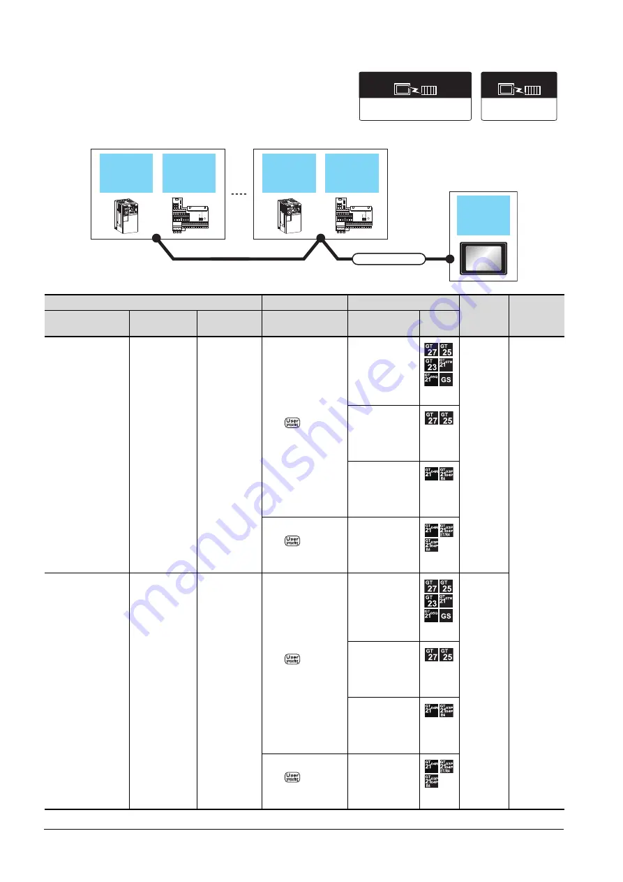
When connecting to multiple inverters (Max. 31) (Using the built-in RS485 terminal block)
Inverter
Connection cable
GOT
Max.
distance
Number of
connectable
equipment
Model name
*3
Control terminal
option
Communication
type
Connection diagram
number
Option device
*4
Model
FREQROL-
A700/F700/F700P/
A800/F800/A800 Plus
(Built-in RS485
terminal block)
-
RS-485
- (Built into GOT)
*2
500m
31 inverters
for one GOT
*1
GT15-RS4-9S
GT10-C02H-9SC
- (Built into GOT)
FREQROL-A800-E A8ERS
RS-485
- (Built into GOT)
*2
500m
GT15-RS4-9S
GT10-C02H-9SC
- (Built into GOT)
FREQROL 500/700/800,
SENSORLESS SERVO
Communication driver
FREQROL 800
Communication driver
(For automatic
connection)
GOT
Connection cable
Control
terminal
option
Control
terminal
option
Inverter
Sensorless
servo
Inverter
Sensorless
servo
Summary of Contents for GOT2000 Series
Page 2: ......
Page 84: ......
Page 432: ...6 58 6 6 Precautions ...
Page 578: ...9 54 9 6 Precautions ...
Page 726: ...12 84 12 5 Precautions ...
Page 756: ......
Page 822: ...14 66 14 4 Device Range that Can Be Set ...
Page 918: ...15 96 15 7 Precautions ...
Page 930: ...16 12 16 6 Precautions ...
Page 964: ......
Page 1002: ...19 38 19 7 Precautions ...
Page 1022: ...20 20 20 5 Precautions ...
Page 1023: ...MULTI CHANNEL FUNCTION 21 MULTI CHANNEL FUNCTION 21 1 ...
Page 1024: ......
Page 1054: ...21 30 21 5 Multi channel Function Check Sheet ...
Page 1055: ...FA TRANSPARENT FUNCTION 22 FA TRANSPARENT FUNCTION 22 1 ...
Page 1056: ......
Page 1223: ......