14.2 System Configuration
14 - 25
INVERTER
C
O
NNE
CTION
14
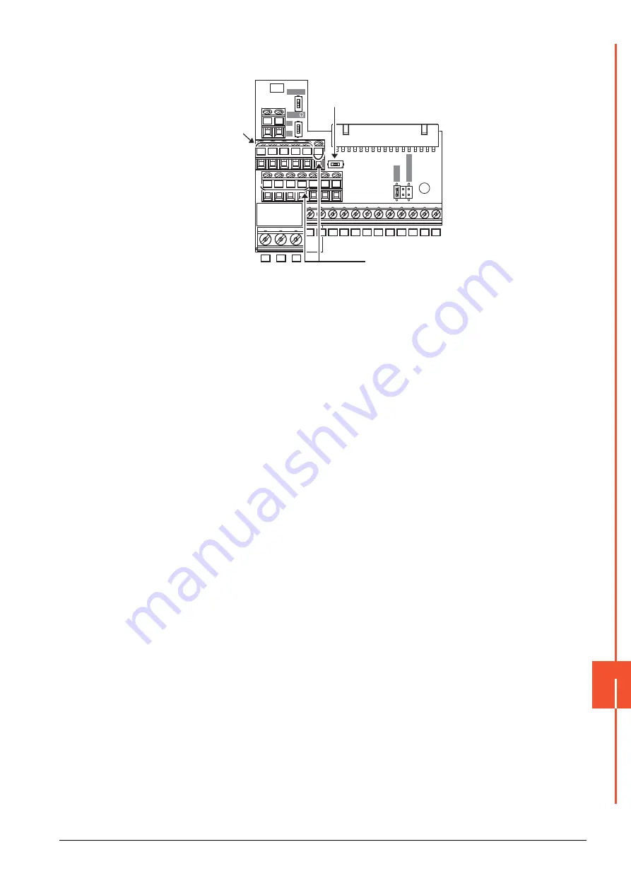
(5) Terminal block layout in the FR-E7TR control terminal option
Mount the FR-E7TR to the E700 series and the sensorless servo (FREQROL-E700EX series).
■3.
Connecting terminating resistors
(1) GOT side
When connecting a PLC to the GOT, a terminating resistor must be connected to the GOT.Set the terminating
resistor setting switch.
For the procedure to set the terminating resistor, refer to the following.
➠
1.4.3 Terminating resistors of GOT
O
N
OPEN
OPEN
100
100
S
O
URCE
S
O
URCE
SIN
K
SIN
K
V
II
SE
SDA SDB RDA RDB SG
2
SDA SDB
RDA
RDB
SG
2
SDA SDB RDA RDB RUN FU
SDA
SDB
RDA RDB RUN
FU
SE
10
4
RM RH MRS RES
SD
PC
STF
STR
SD
SD
A
B
C
FM
RL
To the GOT or
the previous
inverter
Set the terminal 2/SG switch to the
right position (ON) to change the
terminal 2 to the terminal SG.
To the next inverter
Summary of Contents for GOT2000 Series
Page 2: ......
Page 84: ......
Page 432: ...6 58 6 6 Precautions ...
Page 578: ...9 54 9 6 Precautions ...
Page 726: ...12 84 12 5 Precautions ...
Page 756: ......
Page 822: ...14 66 14 4 Device Range that Can Be Set ...
Page 918: ...15 96 15 7 Precautions ...
Page 930: ...16 12 16 6 Precautions ...
Page 964: ......
Page 1002: ...19 38 19 7 Precautions ...
Page 1022: ...20 20 20 5 Precautions ...
Page 1023: ...MULTI CHANNEL FUNCTION 21 MULTI CHANNEL FUNCTION 21 1 ...
Page 1024: ......
Page 1054: ...21 30 21 5 Multi channel Function Check Sheet ...
Page 1055: ...FA TRANSPARENT FUNCTION 22 FA TRANSPARENT FUNCTION 22 1 ...
Page 1056: ......
Page 1223: ......


