14.3 Ethernet Connection
14 - 49
INVERTER
C
O
NNE
CTION
14
■4.
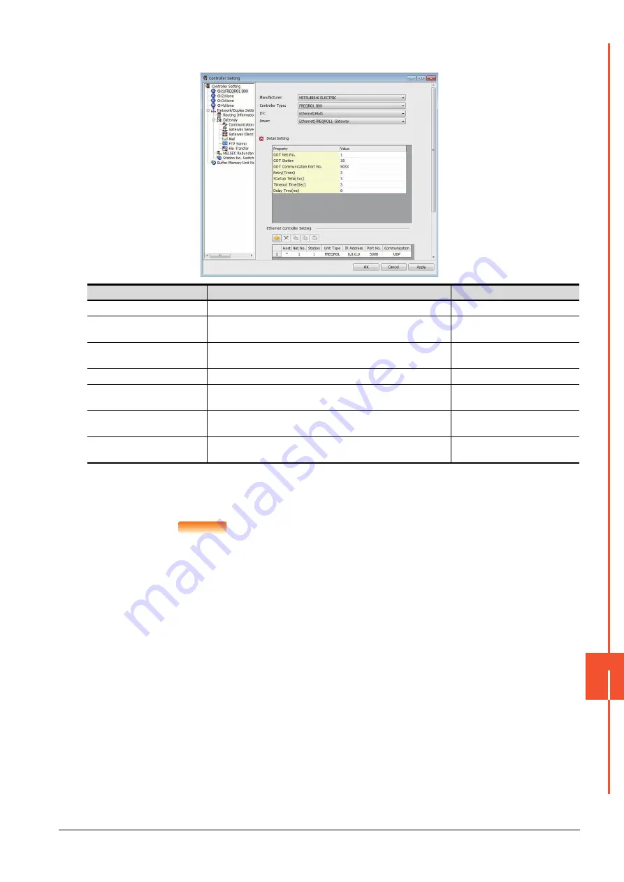
Ethernet setting
*1
Each of [GOT Station] set in the communication detail setting and [Station] set in the Ethernet setting must be set to different
station numbers.
➠ ■2.
POINT
POINT
POINT
(1) Communication interface setting by the Utility
The communication interface setting can be changed on the Utility's [Communication setting]
after writing [Controller Setting] of project data.
For details on the Utility, refer to the following manual.
➠
GOT2000 Series User's Manual (Utility)
(2) Precedence in communication settings
When settings are made by GT Designer3 or the Utility, the latest setting is effective.
Item
Description
Set value
Host
The host is displayed. (The host is indicated with an asterisk (*).)
-
N/W No.
Set the network No. of the connected Ethernet module.
(Default: blank)
1 to 239
Station
*1
Set the station No. of the connected Ethernet module.
(Default: blank)
1 to 120
Unit Type
FREQROL (fixed)
FREQROL (fixed)
IP Address
Set the IP address of the connected Ethernet module.
(Default: blank)
Inverter side IP address
Port No.
Set the port No. of the connected Ethernet module.
(Default: 5008)
Inverter side port No.
Communication
UDP, TCP
(Default: UDP)
Adjust the settings with the Inverter
settings.
Summary of Contents for GOT2000 Series
Page 2: ......
Page 84: ......
Page 432: ...6 58 6 6 Precautions ...
Page 578: ...9 54 9 6 Precautions ...
Page 726: ...12 84 12 5 Precautions ...
Page 756: ......
Page 822: ...14 66 14 4 Device Range that Can Be Set ...
Page 918: ...15 96 15 7 Precautions ...
Page 930: ...16 12 16 6 Precautions ...
Page 964: ......
Page 1002: ...19 38 19 7 Precautions ...
Page 1022: ...20 20 20 5 Precautions ...
Page 1023: ...MULTI CHANNEL FUNCTION 21 MULTI CHANNEL FUNCTION 21 1 ...
Page 1024: ......
Page 1054: ...21 30 21 5 Multi channel Function Check Sheet ...
Page 1055: ...FA TRANSPARENT FUNCTION 22 FA TRANSPARENT FUNCTION 22 1 ...
Page 1056: ......
Page 1223: ......


