


14 - 64
14.4 Device Range that Can Be Set
■3.
Inverter (FREQROL 800 series)
(Automatic connection)
*1
Only 16-bit (1-word) designation is possible.
*2
Only reading is possible.
*3
When the GOT is connected to the PU connector and the operation mode is set to the PU operation mode, the multi-speed
operation (W3 to W7, SP121, SP122) cannot be used.
For using the multi-speed operation, follow either of the operations as below.
• Connect the GOT to the RS-485 terminal and set the operation mode to the NET operation mode (Computer link operation
mode), and then operate the inverter.
• Change the motor speed with the set frequency (SP109, SP110), and then operate the inverter with the forward or reverse
rotation (WS1, WS2, SP121, SP122).
*4
Only writing is possible for WS devices.
More than one WS cannot turn on at once.
(Except the turned on WS device, the other WS devices turn off.)
Bits of SP122 (word device) and SP121 (word device) are assigned to WS0 to WS7 and WS8 to WS15 respectively.
When more than one WS turns on at once, convert the values for the bit devices that are assigned to the word device into values
for the word device. Write the converted values into SP122 or SP121.
• Setting High speed operation command (WS5), Middle speed operation command (WS4), and Low speed operation command
(WS3)
When setting High speed operation command (WS5), Middle speed operation command (WS4), and Low speed operation
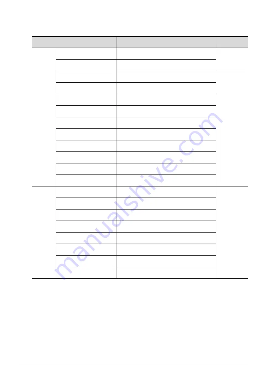
Device name
Setting range
Device
No. representation
Bit device
Inverter status monitor (RS)
*2
0-0 RS0 to 0-31 RS15
0-100 RS0 to 0-115 RS15
Decimal
Run command (WS)
*3*4
0-0 WS0 to 0-31 WS15
0-100 WS0 to 0-115 WS15
Input (X)
0-0 X00 to 0-31 X7F
0-100 X00 to 0-115 X7F
Hexadecimal
Output (Y)
0-0 Y00 to 0-31 Y7F
0-100 Y00 to 0-115 Y7F
Internal relay (M)
0-0 M0 to 0-31 M127
0-100 M0 to 0-115 M127
Decimal
Timer Coil (TC)
0-0 TC0 to 0-31 TC15
0-100 TC0 to 0-115 TC15
Timer Contact (TT)
0-0 TT0 to 0-31 TT15
0-100 TT0 to 0-115 TT15
Counter Coil (CC)
0-0 CC0 to 0-31 CC15
0-100 CC0 to 0-115 CC15
Counter Contact (CT)
0-0 CT0 to 0-31 CT15
0-100 CT0 to 0-115 CT15
Retentive timer Coil (SC)
0-0 SC0 to 0-31 SC15
0-100 SC0 to 0-115 SC15
Retentive timer Contact (SS)
0-0 SS0 to 0-31 SS15
0-100 SS0 to 0-115 SS15
Special relay (SM)
*5
0-0 SM0 to 0-31 SM2047
0-100 SM0 to 0-115 SM2047
Word device
Alarm definition (A)
*1*2
0-0 A0 to 0-31 A7
0-100 A0 to 0-115 A7
Decimal
Parameter (Pr)
*1
0-0 Pr0 to 0-31 Pr1500
0-100 Pr0 to 0-115 Pr1500
Special parameter (SP)
*1*3*4
0-0 SP108 to 0-31 SP127
0-100 SP108 to 0-115 SP127
Timer current value (TN)
0-0 TN0 to 0-31 TN15
0-100 TN0 to 0-115 TN15
Counter current value (CN)
0-0 CN0 to 0-31 CN15
0-100 CN0 to 0-115 CN15
Retentive timer current value (SN)
0-0 SN0 to 0-31 SN15
0-100 SN0 to 0-115 SN15
Data register (D)
0-0 D0 to 0-31 D255
0-100 D0 to 0-115 D255
Special data register (SD)
0-0 SD0 to 0-31 SD2047
0-100 SD0 to 0-115 SD2047
Summary of Contents for GOT2000 Series
Page 2: ......
Page 84: ......
Page 432: ...6 58 6 6 Precautions ...
Page 578: ...9 54 9 6 Precautions ...
Page 726: ...12 84 12 5 Precautions ...
Page 756: ......
Page 822: ...14 66 14 4 Device Range that Can Be Set ...
Page 918: ...15 96 15 7 Precautions ...
Page 930: ...16 12 16 6 Precautions ...
Page 964: ......
Page 1002: ...19 38 19 7 Precautions ...
Page 1022: ...20 20 20 5 Precautions ...
Page 1023: ...MULTI CHANNEL FUNCTION 21 MULTI CHANNEL FUNCTION 21 1 ...
Page 1024: ......
Page 1054: ...21 30 21 5 Multi channel Function Check Sheet ...
Page 1055: ...FA TRANSPARENT FUNCTION 22 FA TRANSPARENT FUNCTION 22 1 ...
Page 1056: ......
Page 1223: ......


