


8 - 46
8.4 Precautions
■2.
Power-On sequence for GOT and Q4ARCPU redundant system
Apply the power to the GOT and Q4ARCPU redundant system in the following sequence.
Step 1.
Turn ON the GOT.
Step 2.
After the monitor screen is displayed on the GOT, turn ON the Q4ARCPU redundant system.
At this time, a timeout is displayed on the system alarm. Use System Information to reset the alarm.
For the system alarm, refer to the following manual:
➠
GT Designer3 (GOT2000) Screen Design Manual
8.4.15
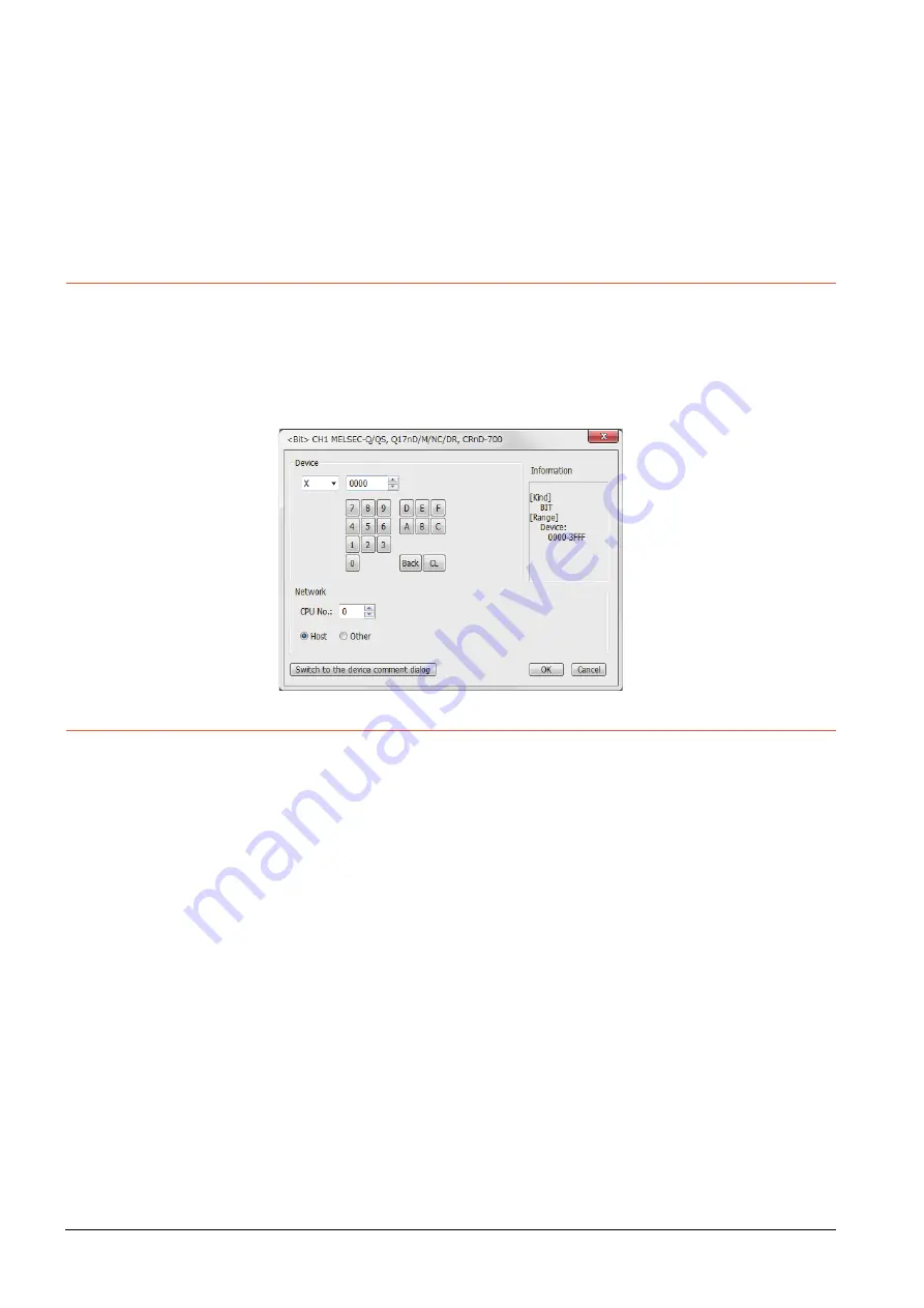
When monitoring the Q170MCPU, Q170MSCPU(-S1)
Set [CPU No.] to "2" in the device setting to monitor the device of the Motion CPU area (CPU No.2).
When the CPU No. is set to "0" or "1", the device on the PLC CPU area (CPU No.1) is monitored.
When the CPU No. is set to the number other than "0" to "2", a communication error occurs and the monitoring cannot be
executed.
For setting the CPU No., refer to the following manual.
➠
GT Designer3 (GOT2000) Screen Design Manual
Example) Setting dialog box of the bit device
8.4.16
Troubleshooting
For the troubleshooting, refer to the User's Manual for the GOT you are using.
Summary of Contents for GOT2000 Series
Page 2: ......
Page 84: ......
Page 432: ...6 58 6 6 Precautions ...
Page 578: ...9 54 9 6 Precautions ...
Page 726: ...12 84 12 5 Precautions ...
Page 756: ......
Page 822: ...14 66 14 4 Device Range that Can Be Set ...
Page 918: ...15 96 15 7 Precautions ...
Page 930: ...16 12 16 6 Precautions ...
Page 964: ......
Page 1002: ...19 38 19 7 Precautions ...
Page 1022: ...20 20 20 5 Precautions ...
Page 1023: ...MULTI CHANNEL FUNCTION 21 MULTI CHANNEL FUNCTION 21 1 ...
Page 1024: ......
Page 1054: ...21 30 21 5 Multi channel Function Check Sheet ...
Page 1055: ...FA TRANSPARENT FUNCTION 22 FA TRANSPARENT FUNCTION 22 1 ...
Page 1056: ......
Page 1223: ......


