18.3 Connection Diagram
18 - 3
18
LASE
R DISPLACE
MENT SEN
SOR MH1
1 CONN
ECTION
18.3 Connection Diagram
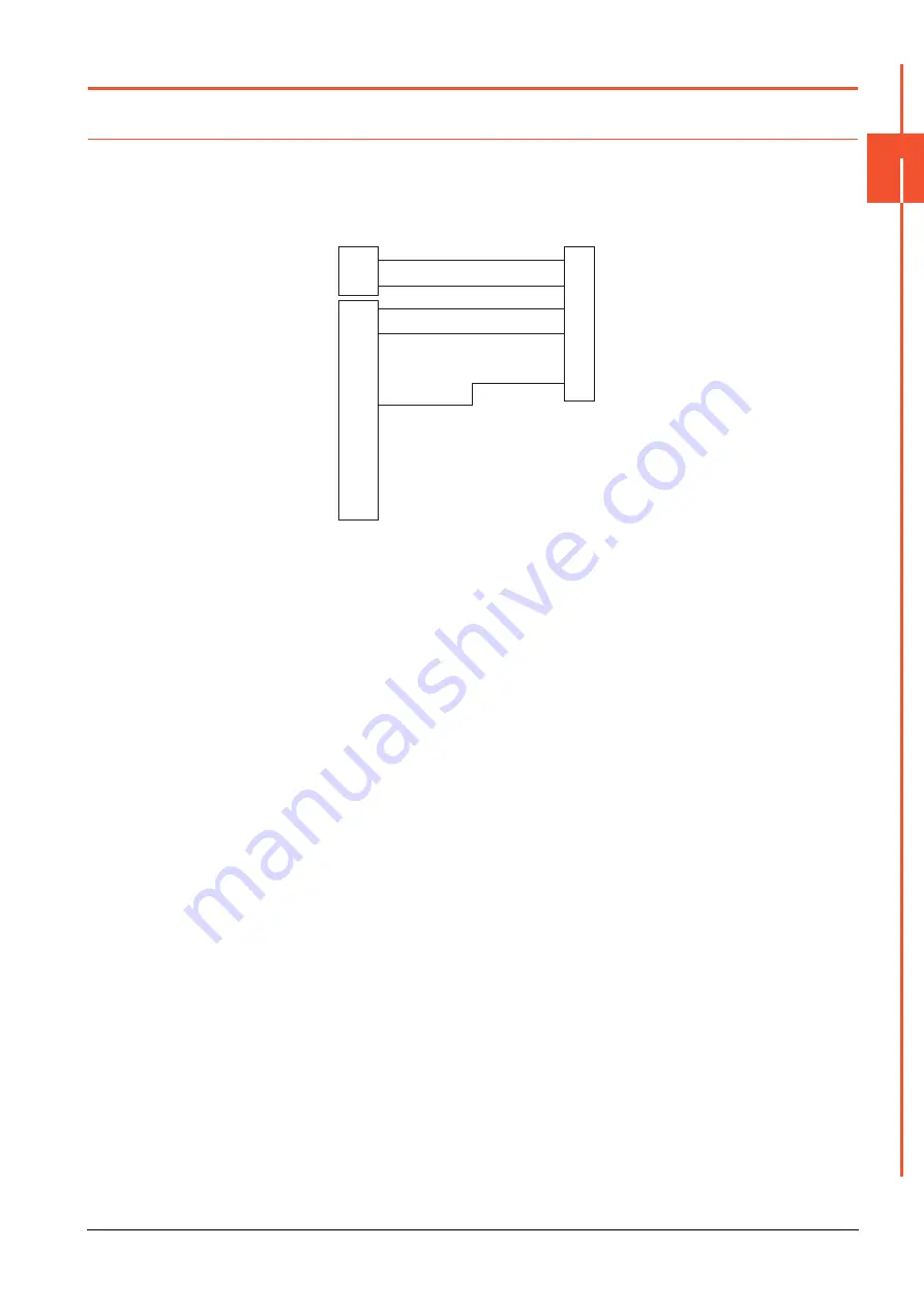
The following diagram shows the connection between the GOT and the Controller.
18.3.1
RS-232 cable
■1.
Connection Diagram
(1) RS-232 connection diagram 1)
■2.
Precautions when preparing a cable
(1) Cable length
The length of the RS-232 cable must be within the maximum distance specifications.
(2) GOT side connector
For the GOT side connector, refer to the following.
➠
1.4.1 GOT connector specifications
GOT side
(terminal block)
Untied wire color
of MH11C30R2
White
Black
Green
Red
Yellow
SD
RD
ER
DR
SG
RS
CS
NC
NC
24V+
24V-
Summary of Contents for GOT2000 Series
Page 2: ......
Page 84: ......
Page 432: ...6 58 6 6 Precautions ...
Page 578: ...9 54 9 6 Precautions ...
Page 726: ...12 84 12 5 Precautions ...
Page 756: ......
Page 822: ...14 66 14 4 Device Range that Can Be Set ...
Page 918: ...15 96 15 7 Precautions ...
Page 930: ...16 12 16 6 Precautions ...
Page 964: ......
Page 1002: ...19 38 19 7 Precautions ...
Page 1022: ...20 20 20 5 Precautions ...
Page 1023: ...MULTI CHANNEL FUNCTION 21 MULTI CHANNEL FUNCTION 21 1 ...
Page 1024: ......
Page 1054: ...21 30 21 5 Multi channel Function Check Sheet ...
Page 1055: ...FA TRANSPARENT FUNCTION 22 FA TRANSPARENT FUNCTION 22 1 ...
Page 1056: ......
Page 1223: ......


