


19.3 System Configuration
19 - 21
19
GOT MUL
T
I-DR
OP CONNEC
T
ION
19.3 System Configuration
*1
Connect it to the RS-422/485 interface (built into GOT).
*2
The maximum distance from the PLC to the terminal GOT.
*3
When the number of connected GOTs is increased, the response performance decreases.
*4
GT25-W does not support the option device.
*5
GT2505-V does not support the option device other than GT10-9PT5S and GT14-RS2T4-9P.
*6
GT2505-V?GT2105-Q only supported.
*7
Connect it to the RS-232 interface (built into GOT).
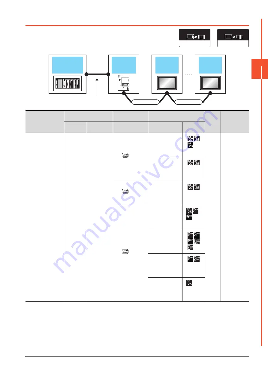
PLC
Serial Multi-Drop Connection
Unit
Connection cable
GOT
Max.
distance
Number of
connectable
equipment
Model
Communication
type
Cable model
Option device
*4*5
Model
For details of the system
configuration between
the Serial Multi-Drop
Connection Unit and
PLC, refer to the
corresponding section.
GT01-RS4-M
RS-485
- (Built into GOT)
500m
*2
16 GOTs for
Serial Multi-Drop
Connection Unit
*3
GT15-RS4-9S
GT15-RS4-TE
GT10-9PT5S
*1
*6
- (Built into GOT)
GT10-C02H-9SC
GT14-RS2T4-9P
*7
*6
(Serial Multi-Drop Connection Unit)
Connection type
dependent
Communication driver
(GOT)
Multi-Drop (Slave)
Communication driver
Connection cable
GOT
GOT
Serial multi
drop connection
unit
PLC
Varies according to the
connection type.
Connection cable
Summary of Contents for GOT2000 Series
Page 2: ......
Page 84: ......
Page 432: ...6 58 6 6 Precautions ...
Page 578: ...9 54 9 6 Precautions ...
Page 726: ...12 84 12 5 Precautions ...
Page 756: ......
Page 822: ...14 66 14 4 Device Range that Can Be Set ...
Page 918: ...15 96 15 7 Precautions ...
Page 930: ...16 12 16 6 Precautions ...
Page 964: ......
Page 1002: ...19 38 19 7 Precautions ...
Page 1022: ...20 20 20 5 Precautions ...
Page 1023: ...MULTI CHANNEL FUNCTION 21 MULTI CHANNEL FUNCTION 21 1 ...
Page 1024: ......
Page 1054: ...21 30 21 5 Multi channel Function Check Sheet ...
Page 1055: ...FA TRANSPARENT FUNCTION 22 FA TRANSPARENT FUNCTION 22 1 ...
Page 1056: ......
Page 1223: ......


