


This manual confers no industrial property rights or any rights of any other
kind, nor does it confer any patent licenses. Mitsubishi Electric Corporation
cannot be held responsible for any problems involving industrial property rights
which may occur as a result of using the contents noted in this manual.
Warranty
Mitsubishi will not be held liable for damage caused by factors found not to be
the cause of Mitsubishi; opportunity loss or lost profits caused by faults in the
Mitsubishi products; damage, secondary damage, accident compensation
caused by special factors unpredictable by Mitsubishi; damages to products
other than Mitsubishi products; and to other duties.
For safe use
This product has been manufactured as a general-purpose part for general
industries, and has not been designed or manufactured to be incorporated in
a device or system used in purposes related to human life.
Before using the product for special purposes such as nuclear power, electric
power, aerospace, medicine or passenger movement vehicles, consult with
Mitsubishi Electric.
This product has been manufactured under strict quality control. However
when installing the product where major accidents or losses could occur if the
product fails, install appropriate backup or failsafe functions in the system.
HEAD OFFICE : TOKYO BUILDING, 2-7-3 MARUNOUCHI, CHIYODA-KU, TOKYO 100-8310, JAPAN
7. Function specification
7.1 Transfer function
: Available to transfer
: Unavailable to transfer
*1 Ver.01.08.00 or later of the standard monitor OS of the GT10 is applicable.
*2 Ver.01.11.00 or later of the standard monitor OS of the GT10 is applicable.
*3 Ver. 2.91V or later of GT Designer2 or Ver. 1.01B or later of GT Designer3 are
applicable.
*4 It takes longer time to transfer the font data than to transfer the standard
monitor OS and communication driver.
(It takes approximately 1 minute and 45 seconds to transfer "Standard
monitor OS + Communication driver". It takes approximately 8 minutes to
transfer "Standard monitor OS + Communication Font data".)
Japanese (supporting Europe) is installed in the GT10 before shipment from
the factory.
It is not necessary to transfer the font data when the used font is not changed.
7.2 Password reset function on the GOT
When reading out the project data from the memory loader, if the password is set in
the project data, password entry screen will appear on the GOT.
After entering the password, password is reset by pressing the ENT key on the
screen. The data will be transferred from the GOT to the memory loader.
The operation procedure is described below.
When this function is used, Ver.01.08.00 or later of the standard monitor OS of the
GT10 is required.
1) When the upload is started, password
entry screen will appear on the GOT
Touch the "INPUT" key.
2) After inputting password, touch the "ENT"
key.
3) When the password matches, a message
notifying Password correct is display.
Touch the
button to close the
screen.
When the password does not match, an
error message is displayed.
If
button is touch it returns to the
password input screen again.
7.3 Error display function
If an error occurs between the GOT and the memory loader during the transfer, an
error message will appear on the GOT screen.
Apply remedies according to the display.
Chapter 12 Troubleshooting
Turning OFF and ON the power or touching the screen will close the error message
screen.
When this function is used, Ver.01.08.00 or later of the standard monitor OS of the
GT10 is required.
Transfer direction
Data
selection
switch
Transfer data
Operation
Project
data
Resource
data
Standard
monitor OS
Font
data
*2
Communication
driver
1) PC
Memory loader
--
*3
After all data in the memory loader is deleted, the data
selected with GT Designer2 or GT Designer3 is written
to the memory loader all at once.
2) Memory loader
PC
--
The project data or resource data is read out from the
memory loader to a PC.
3) Memory loader
GOT
P
OS
*4
All data in the memory loader is written to the GOT.
PROJECT
Only the project data in the memory loader is written
to the GOT.
4) GOT
Memory loader
P
OS*
1
After all data in the memory loader is deleted, all data
in the GOT is read out to the memory loader.
PROJECT
After all data in the memory loader is deleted, only the
project data and resource data in the GOT are read
out to the memory loader.
Standard monitor OS
Font data
Communication driver
Project data
Standard monitor OS
Font data
Communication driver
Project data
PC
(GT Designer2, GT Designer3)
Project data
Resource data
Memory loader
Standard monitor OS
Communication driver
Project data
Resource data
GT1020, GT1030
1)
2)
4)
3)
ESC
OK
Error message on the GOT
8. Installation of Driver, Setting Software
When the communication between a PC (GT Designer2 Ver.2.77F or later, GT
Designer3 Ver.1.01B or later) and the memory loader is performed, driver
installation, communication port setting is required.
8.1 Driver installation
When the communication between a PC (GT Designer2, GT Designer3) and the
memory loader is performed, driver installation is required. Refer to the following
manual for details about driver installation.
GT Designer2 Version Basic Operation/Data Transfer Manual
GT Designer3 Version Screen Design Manual (Fundamentals)
8.2 Confirmation of communication port
Windows
®
XP example follows.
In Windows
®
XP, click [ Start ]
[ Settings ]
[ Control Panel ]
[ Performance and Maintenance ]
[ System ]
[ Hardware ]
[ Device
Manager (D) ] and the window below will be displayed.
Please confirm the COM number to which the USB driver is allocated (COM and
LPT).
If using Windows
®
98, Windows
®
98SE, Windows
®
Millennium Edition or
Windows
®
2000
A screen that is equivalent to the one below is displayed by clicking [ My
Computer ]
[ Control Panel ]
[ System ]
[ Device Manager ] in the
menu of the personal computer.
If using Windows
®
Vista. A screen that is equivalent to the one below is
displayed by clicking [ Start ]
[ Control Panel ]
[ Device Manager ] in the
menu of the personal computer.
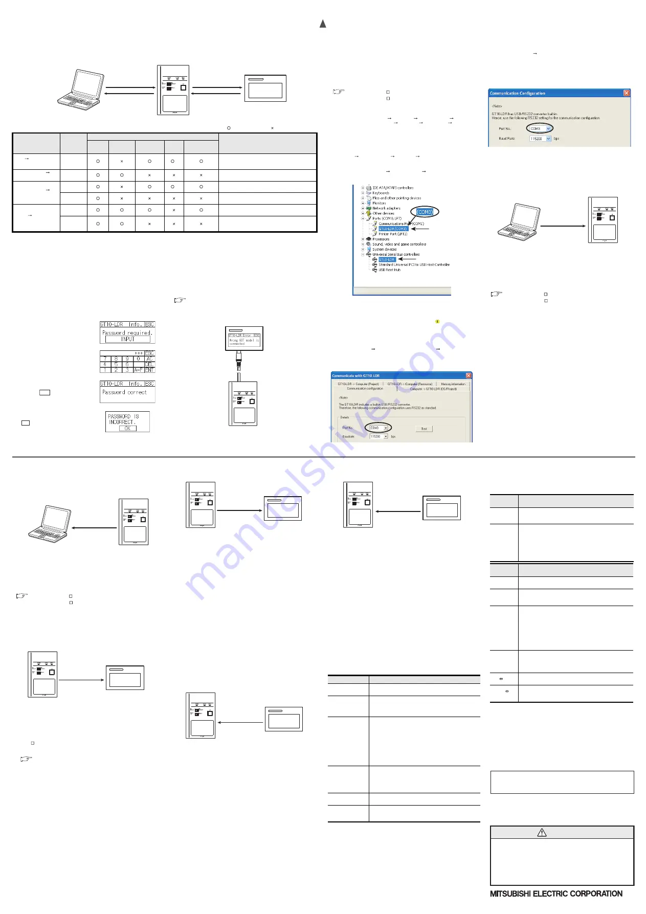
Check following:
- GT10-LDR is indicated at A).
- GT10-LDR (COM *) is indicated at B).
* indicates the COM number used in Memory loader.
- Install the GT Designer2 or GT Designer3 again when
is displayed.
Select the GT Designer2 or GT Designer3 COM number as the COM number
currently assigned on the screen above.
8.3 Setting GT Designer2
Click [ Communication ]
[ Communicate with GT10-LDR ]
[ Communication
configuration tab ].
Select the same COM number as the COM number of the personal computer when
the setting communication port screen appears.
Click [ Update ].
8.4 Setting GT Designer3
Click [ Communication ]
[ Communicate with GT10-LDR... ] to display the
communicate with GT10-LDR screen.
Click the [ Communication Configuration... ] tab to display the communication
configuration dialog.
Select the same COM number as the COM number of the personal computer when
the setting communication port screen appears.
Click [ OK ].
9. Transfer procedures between a PC and the Memory
loader
9.1 To write the data from a PC (GT Designer2 Ver.2.77F or later,
GT Designer3 Ver.1.01B or later) to the memory loader
The standard monitor OS, communication driver, font data, and project data are
written from a PC (GT Designer2, GT Designer3) to the memory loader. The
operation procedure is described below.
1) Turn OFF the Write protection switch.
2) Connect a PC (GT Designer2, GT Designer3) to the memory loader with USB
cable supplied.
3) Write the data from a PC (GT Designer2, GT Designer3) to the memory loader.
Refer to the following manual for details about operating instructions of GT
Designer2 or GT Designer3.
GT Designer2 Version Basic Operation/Data Transfer Manual
GT Designer3 Version Screen Design Manual (Fundamentals)
A)
B)
Memory loader
Standard monitor OS
Communication driver
Font data
Project data
PC
(GT Designer2, GT Designer3)
9.2 To read out the data from the memory loader to a PC (GT
Designer2 Ver.2.77F or later, GT Designer3 Ver.1.01B or
later).
The project data and resource data are read out from the memory loader to a PC
(GT Designer2, GT Designer3). The operation procedure is described below.
1) Connect a PC (GT Designer2, GT Designer3) to the memory loader with USB
cable supplied.
2) Select the data to be uploaded in a PC (GT Designer2, GT Designer3) and read it
out from the memory loader.
Refer to the following manual for details about operating instructions of GT
Designer2 or GT Designer3.
GT Designer2 Version Basic Operation/Data Transfer Manual
GT Designer3 Version Screen Design Manual (Fundamentals)
10. To write the data from the Memory loader to the GOT
The standard monitor OS, communication driver, font data, and project data are
written from the memory loader to the GOT. The operation procedure is described
below.
10.1 When the Data selection switch is [P OS]
1) Connect the memory loader to the GOT.
2) Turn ON the GOT by pressing the lower right corner of the GOT.
(The GOT startups with OS installation screen.)
The OS can be transferred from GT Designer2 Version2 or GT Designer3
Version without displaying the OS installation screen depending on the
combination of the GOT and the standard monitor OS.
Refer to the following manual for details about OS installation screen.
GT10 User's Manual
3) Set the Data selection switch to [P OS] and the RD/WR selection
switch to [WR], and select the data to be transferred and transfer direction.
4) Press the ENT key to determine the data to be transferred and transfer direction.
(SET/RUN LED will be orange.)
*: If the next operation is not performed within 30 seconds after the ENT key is
pressed, SET/RUN LED will be unlit, and the operations that have been made will
be canceled.
*: When the Data selection switch or the RD/WR selection switch is operated,
after the data to be transferred and the transfer direction are determined, the
operations that have been made will be canceled.
5) Press the ENT key again to start the transfer. (SET/RUN LED will be green
flashing.)
6) Turn OFF the GOT and remove the memory loader after the transfer is
completed. (SET/RUN LED will be green flashing.)
Refer to the "Chapter 12 Troubleshooting" for details on handling errors during
transferring.
10.2 When the Data selection switch is [PROJECT]
1) Connect the memory loader to the GOT and turn ON the GOT.
2) Set the Data selection switch to [PROJECT] and the RD/WR selection switch to
[WR], and select the data to be transferred and transfer direction.
3) Press the ENT key to determine the data to be transferred and transfer direction.
(SET/RUN LED will be orange.)
*: If the next operation is not performed within 30 seconds after the ENT key is
pressed, SET/RUN LED will be unlit, and the operations that have been made will
be canceled.
*: When the Data selection switch or the RD/WR selection switch is operated,
after the data to be transferred and the transfer direction are determined, the
operations that have been made will be canceled.
4) Press the ENT key again to start the transfer. (SET/RUN LED will be green
flashing.)
5) Turn OFF the GOT and remove the memory loader after the transfer is
completed. (SET/RUN LED will be green flashing.)
Refer to the "Chapter 12 Troubleshooting" for details on handling errors during
transferring.
11. To read out the data from the GOT to the Memory
loader
The standard monitor OS, communication driver, project data, and resource data
are read out from the GOT to the memory loader. The operation procedure is
described below.
11.1 When the Data selection switch is [P OS]
1) Turn OFF the Write protection switch.
2) Connect the memory loader to the GOT and turn ON the GOT.
3) Set the Data selection switch to [P OS] and the RD/WR selection
switch to [RD], and select the data to be transferred and transfer direction.
4) Press the ENT key to determine the data to be transferred and transfer direction.
(SET/RUN LED will be orange.)
*: If the next operation is not performed within 30 seconds after the ENT key is
pressed, SET/RUN LED will be unlit, and the operations that have been made will
be canceled.
*: When the Data selection switch or the RD/WR selection switch is operated,
after the data to be transferred and the transfer direction are determined, the
operations that have been made will be canceled.
5) Press the ENT key again to start the transfer. (SET/RUN LED will be green
flashing.)
6) Turn OFF the GOT and remove the memory loader after the transfer is
completed. (SET/RUN LED will be green flashing.)
Refer to the "Chapter 12 Troubleshooting" for details on handling errors during
transferring.
PC
(GT Designer2, GT Designer3)
Memory loader
Project data
Resource data
Standard monitor OS
Communication driver
Font data
Project data
Memory loader
GT1020, GT1030
Project data
Memory loader
GT1020, GT1030
Project data
Communication driver
Standard monitor OS
Resource data
Memory loader
GT1020, GT1030
11.2 When the Data selection switch is [PROJECT]
1) Turn OFF the Write protection switch.
2) Connect the memory loader to the GOT and turn ON the GOT.
3) Set the Data selection switch to [PROJECT] and the RD/WR selection switch to
[RD], and select the data to be transferred and transfer direction.
4) Press the ENT key to determine the data to be transferred and transfer direction.
(SET/RUN LED will be orange.)
*: If the next operation is not performed within 30 seconds after the ENT key is
pressed, SET/RUN LED will be unlit, and the operations that have been made will be
canceled.
*: When the Data selection switch or the RD/WR selection switch is operated, after
the data to be transferred and the transfer direction are determined, the operations
that have been made will be canceled.
5) Press the ENT key again to start the transfer. (SET/RUN LED will be green flashing.)
6) Turn OFF the GOT and remove the memory loader after the transfer is completed.
(SET/RUN LED will be green flashing.)
Refer to the "Chapter 12 Troubleshooting" for details on handling errors during
transferring.
12. Troubleshooting
12.1 GOT error message
When communication between the GOT and the memory loader does not work, check
the following contents depending on the GOT error messages.
GOT error message
Remedy
Write protection
switch is ON
Write protection switch ON
Turn OFF the Write protection switch.
Wrong GOT model is
connected
The GOT type that is set in the data to be transferred differs
from that of the GOT to which the data is transferred.
Check the GOT type to which the memory loader is
connected.
Corrupt data or OS
version variance
The data to be transferred is broken, or the major version of
the standard monitor OS is different from that of the project
data.
Write the standard monitor OS, communication driver, and
project data from GT Designer2 or GT Designer3 to the
memory loader again, and then transfer them to the GOT
again.
Set the Data selection switch to [P OS] and
read out all data from the GOT to the memory loader, and
then transfer them to the GOT again.
Communication error
Communication error occurs between the GOT and the
memory loader.
Check the connection with the communication cable.
Check that power supply is stable. (lighting of POWER
LED)
GOT contains a
system password
Password is set in the project data.
Reset the password with the numeric keypad on the GOT.
OS installation
screen isn’t active
OS installation screen is not active
Install the data after the OS installation screen is displayed on
the GOT.
Project data
Resource data
Memory loader
GT1020, GT1030
12.2 LED display on the memory loader
If communication cannot be established between the GOT and a PC using
memory loader, confirm the following status by checking display LED in memory
loader.
State of
POWER LED
Contents
POWER LED
is lit.
The DC5V power supply from the GOT or the personal
computer is normally supplied. In case of no communication,
check the status of ERROR LED.
POWER LED
is not lit.
The DC 5V power supply from the GOT or the personal
computer is not supplied. Check the items below.
Turn ON the power.
Check the connection with the USB cable.
Check the connection with the GOT.
Check that PLC is not overloaded when PLC supplies the
power to the GOT connected to the memory loader.
State of
ERROR LED
Contents
Green light
Write protection switch ON
Turn OFF the Write protection switch.
Green
flashing
The GOT type that is set in the data to be transferred differs
from that of the GOT to which the data is transferred.
Check the GOT type to which the memory loader is connected.
Red light
The data to be transferred is broken, or the major version of the
standard monitor OS is different from that of the project data.
Write the standard monitor OS, communication driver, and
project data from GT Designer2 or GT Designer3 to the
memory loader again, and then transfer them to the GOT
again.
Set the Data selection switch to [P OS] and read
out all data from the GOT to the memory loader, and then
transfer them to the GOT again.
Red flashing
Communication error occurs between the GOT and the memory
loader.
Check the connection with the communication cable.
Check that power supply is stable. (lighting of POWER LED)
Red
Green
Password is set in the project data.
Reset the password with the numeric keypad on the GOT.
Orange
Green
OS installation screen is not active
Install the data after the OS installation screen is displayed on
the GOT.


