Page 14
MODEL: HD-6000
3. Adjustment Selection
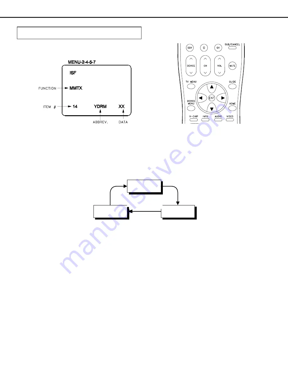
Use the “VIDEO” button to select a specific elecrtrical ajustment.
4. Adjusting Data
After selecting an adjustment item, use the “UP” and “DN” buttons to change adjustment data.
ª If the “UP” button is pressed, the adjustment data increases.
ª If the “DN” button is pressed, the adjustment data decreases.
5. Saving data
Press “ENTER” to save the adjustment data in memory.
The display characters go red for approx. one second in this step.
Note:
If the circuit adjustment mode is terminated without pressing
“ENTER”, changes in adjustment data are not saved.
6. Terminating the circuit adjustment mode
Press the “MENU” button on the remote hand unit twice to terminate the adjustment mode.
Note:
The adjustment mode can be also terminated by turning the
power off.
CIRCUIT ADJUSTMENTS
Electrical Adjustments
Electrical Adjusments are performed in Service Adjustment Mode.
1. Activating the adjustment mode
1. Press the “MENU” button on a remote hand unit.
(The “MENU” display will appear.)
2. Press the buttons “2”, “4”, “5” and “7” in that order. (The screen will change to the adjustment mode.)
If not changed to the adjustment mode, repeat steps 1 and 2.
2. Adjustment Function Selection
Use the “AUDIO” button to select a specific Adjustment Function.
AD9883A
SMTX
MMTX
Functions
Summary of Contents for HD-6000
Page 2: ......
Page 7: ...MODELS HD 6000 Page 7 PWB LOCATIONS Disassembly Sequence ...
Page 8: ...Page 8 MODELS HD 6000 TOP COVER REMOVAL ...
Page 10: ...Page 10 MODELS HD 6000 PWB Removal ...
Page 29: ...MODEL HD 6000 Page 29 Standby Supplies ...
Page 30: ...MODEL HD 6000 Page 30 PWB DM Power Supplies PWB SIGNAL Switched Supplies ...
Page 31: ...MODEL HD 6000 Page 31 VIDEO SELECT CIRCUITRY ...
Page 32: ...MODEL HD 6000 Page 32 VIDEO OUTPUT CIRCUITRY ...
Page 33: ...MODEL HD 6000 Page 33 SYNC SIGNAL SELECTION ...
Page 34: ...MODEL HD 6000 Page 34 Sync Output Path Record Signal Path ...
Page 35: ...MODEL HD 6000 Page 35 Sound Signal Path ...
Page 36: ...MODEL HD 6000 Page 36 CONTROL CIRCUITRY ...
Page 37: ...MODEL HD 6000 Page 37 COMMAND INPUT CIRCUITRY MACROVISION DETECTION ...
Page 38: ...MODEL HD 6000 Page 38 DM Signal Path ...
Page 40: ......


