MODEL: HD-6000
Page 16
Purpose:
Measuring
Instrument
Test Point
Measuring
Range
Input Signal
Ext. Trigger
Input Terminal
Symptom:
Purpose:
Measuring
Instrument
Test Point
Measuring
Range
Input Signal
Ext. Trigger
Input Terminal
Symptom:
[Video Circuit]
1. Main-Y Gain
To set the main picture Y level
Incorrect analog source main picture brightness level.
Oscilloscope
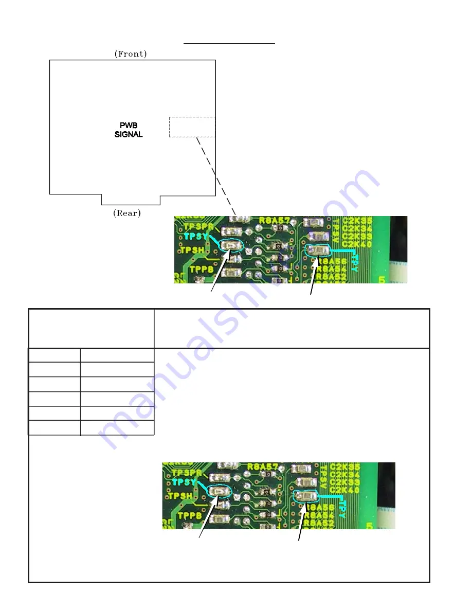
TPY
------
-------
Color bars
External Input
1. Supply a Color Bar pattern with 100% white signal to an External Input. Select
the Color Bars as the source (Device button).
2. Connect a scope to TPY (Main Luminance).
3. Enter the Alignment Mode (MENU-2-4-5-7)
4. Select the MMTX function (AUDIO button).
5. Select adjust item #14 YDRM (VIDEO button).
6. Set the data so the waveform at TPY is 0.7 Vp-p ±0.03 Vp-p (ADJUST buttons).
7. Press “ENTER” to save data.
8. Press “MENU” twice to exit the service mode.
TEST POINTS
TPSY
TPY
PWB-SIGNAL (Partial)
TPSY
TPY
PWB-SIGNAL (Partial)
Summary of Contents for HD-6000
Page 2: ......
Page 7: ...MODELS HD 6000 Page 7 PWB LOCATIONS Disassembly Sequence ...
Page 8: ...Page 8 MODELS HD 6000 TOP COVER REMOVAL ...
Page 10: ...Page 10 MODELS HD 6000 PWB Removal ...
Page 29: ...MODEL HD 6000 Page 29 Standby Supplies ...
Page 30: ...MODEL HD 6000 Page 30 PWB DM Power Supplies PWB SIGNAL Switched Supplies ...
Page 31: ...MODEL HD 6000 Page 31 VIDEO SELECT CIRCUITRY ...
Page 32: ...MODEL HD 6000 Page 32 VIDEO OUTPUT CIRCUITRY ...
Page 33: ...MODEL HD 6000 Page 33 SYNC SIGNAL SELECTION ...
Page 34: ...MODEL HD 6000 Page 34 Sync Output Path Record Signal Path ...
Page 35: ...MODEL HD 6000 Page 35 Sound Signal Path ...
Page 36: ...MODEL HD 6000 Page 36 CONTROL CIRCUITRY ...
Page 37: ...MODEL HD 6000 Page 37 COMMAND INPUT CIRCUITRY MACROVISION DETECTION ...
Page 38: ...MODEL HD 6000 Page 38 DM Signal Path ...
Page 40: ......


