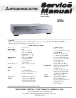
MODEL: HD-6000
Page 3
INTRODUCTION ................................................................................................................................ 5
PRODUCT SAFETY NOTICE ............................................................................................................. 5
SAFETY PRECAUTIONS ................................................................................................................... 6
PWB-LOCATIONS ............................................................................................................................. 7
DISASSEMBLY .................................................................................................................................. 7
Disassembly Procedures Sequence ...................................................................................... 7
Top Cover removal .................................................................................................................. 8
HDD (Hard Drive) removal ....................................................................................................... 9
PWB’S removal ................................................................................................................... 10
ELECTRICAL ADJUSTMENTS ........................................................................................................ 11
Equipment .................................................................................................................................... 11
Option Menu / Initialization Defaults / AV Defaults ......................................................................... 12
LED Diagnostics ........................................................................................................................... 13
Remote Control Operational Mode ................................................................................................ 13
Circuit Adjustment Mode ............................................................................................................... 14
Transfering data ............................................................................................................................ 15
Adjustment Items List ................................................................................................................... 15
Adjustment Procedures ................................................................................................................ 16
Test Points .......................................................................................................................... 16
Main-Y Gain ......................................................................................................................... 16
Sub-Y Gain .......................................................................................................................... 17
Sub Picture Offset ............................................................................................................... 17
CHIP PARTS REPLACEMENT ......................................................................................................... 18
REPLACEMENT PARTS .................................................................................................................. 19
Parts Ordering .............................................................................................................................. 19
Critical and Warranty Parts Designation ........................................................................................ 19
Parts Tolerance Codes .................................................................................................................. 19
SERVICE PARTS LIST .................................................................................................................... 20
CIRCUITRY BLOCK DIAGRAMS ..................................................................................................... 29
Standby Power Supplies ............................................................................................................... 29
PWB-DM Power Supplies ............................................................................................................. 30
PWB-SIGNAL Switched Power Supplies ...................................................................................... 30
Video Select Circuitry ................................................................................................................... 31
Video Output Circuitry ................................................................................................................... 32
Sync Signal Selection ................................................................................................................... 33
Sync Signal Output Path .............................................................................................................. 34
Record Signal Path ....................................................................................................................... 34
Sound Signal Path ........................................................................................................................ 35
Control Circuitry ............................................................................................................................ 36
Command Input Circuitry ............................................................................................................... 37
Macrovision Detection ................................................................................................................... 37
PWB-DM Signal Path ................................................................................................................... 38
CONTENTS
Summary of Contents for HD-6000
Page 2: ......
Page 7: ...MODELS HD 6000 Page 7 PWB LOCATIONS Disassembly Sequence ...
Page 8: ...Page 8 MODELS HD 6000 TOP COVER REMOVAL ...
Page 10: ...Page 10 MODELS HD 6000 PWB Removal ...
Page 29: ...MODEL HD 6000 Page 29 Standby Supplies ...
Page 30: ...MODEL HD 6000 Page 30 PWB DM Power Supplies PWB SIGNAL Switched Supplies ...
Page 31: ...MODEL HD 6000 Page 31 VIDEO SELECT CIRCUITRY ...
Page 32: ...MODEL HD 6000 Page 32 VIDEO OUTPUT CIRCUITRY ...
Page 33: ...MODEL HD 6000 Page 33 SYNC SIGNAL SELECTION ...
Page 34: ...MODEL HD 6000 Page 34 Sync Output Path Record Signal Path ...
Page 35: ...MODEL HD 6000 Page 35 Sound Signal Path ...
Page 36: ...MODEL HD 6000 Page 36 CONTROL CIRCUITRY ...
Page 37: ...MODEL HD 6000 Page 37 COMMAND INPUT CIRCUITRY MACROVISION DETECTION ...
Page 38: ...MODEL HD 6000 Page 38 DM Signal Path ...
Page 40: ......


