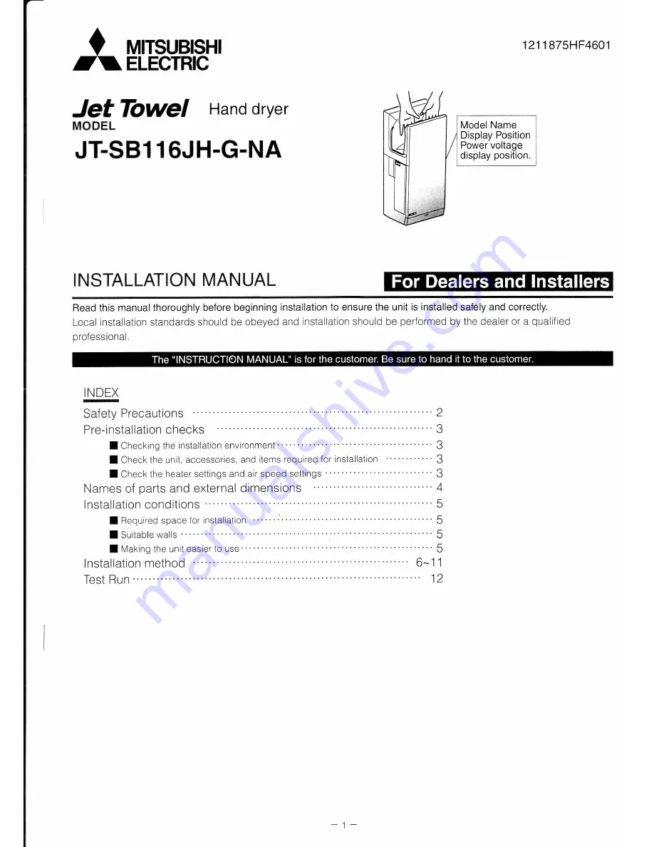
background image

Summary of Contents for Jet Towel JT-SB116JH-G-NA

Page 1: ...and installation should be performed by the dealer or a qualif ied IgEI Safety Precautions 2 Pre installationchecks 3 I Checking the installation environment 3 I Check the unit accessories and items required for installation 3 I Check the heater settings and air speed settings 3 Names of oarts and external dimensions 4 lnstallation conditions 5 I Required space for installation ISuitablewalls 5 l ...

Page 2: ...resent This may cause malfunctions Do not scratch damage process excessively bend pull twist or bundle the power cable and do not place heavy objects onto it or trap it Doing so may damage the power cable causing f tres or electric shocks v Follow instructions Do not attempt any disassembly or modification of the unit that is not expressly stated in this manuat Doing so may result in fires electri...

Page 3: ...rect sunlight or strong light May cause the sensor to malfunction Rooms that have a sterilization basin swimming pools bathrooms I Check the unit accessories and items required for installation Mounting screws 5 x 30 Type 1 tapping screws 7 CPGPGPcflGPaPcfl Service panel mounting screw 1 d Main unit rraintank Screwdriver Longer than 6 150mm Air filter Pen To mark position to insert metal screw plu...

Page 4: ... and l lfTl x ls tL i f E t 1034 263mm external dimensions Refer to the lnstallation conditions on oaoe 5 Electrical Cond uit Tubing I Front I Rear Maintenance switch mHii Front panel mounting screws Power cable hole ...

Page 5: ...Conduit Tubing Leave more than 9 232mm clearance on the left to make maintenance easier Suitable walls Flat walls with no unevenness Walls that can support the weight of the unit Reinforce any walls made with materials other than concrete When installing on a concrete wall use commercially available metal screw anchors Making the unit easier to use Refer to the lnstallation position guide Leave mo...

Page 6: ... Check I tzOV AC power is being used I Make sure that a ground fault circuit interrupter is installed in the fixed wiring X AWG 12 or 14 solid or stranded copper wire is being used for the power cable Make sure that a means for disconnection is incorporated in the fixed wiring in accordance with the wiring rules Follow the illustration on the rioht for the internal wiring o N N r crl 11 1 297 F l ...

Page 7: ...nued 2 Remove the front panel mounting screws 2 and remove the front panel 3 Remove the terminal cover mounting screw 1 and remove the terminal cover X Be careful not to lose the rubber bushinq Front panel mounting screws 7 ...

Page 8: ...ole locations on the back panel mark the 7 drill hole positions on the wall and remove the back panel 5 Drill the 7 holes and insert the 6 enclosed self tapping screws exclude the hole in the lower right corner through the back panel and into the wooden studs To secure the opposite side of the back panel use M6 Toggle Bolts not included due to the heavy weight of the hand dryer Do not use plastic ...

Page 9: ...Green striped bonding wire Power cable Green striped bonding wire Terminal base 1 Run the power cable through the rubber bushing and attach the rubber bushing to the terminal cover 2 Attach the terminal cover to the main unit using the terminal cover mounting screw 3 Move the power cable to the left side of the terminal cover 4 Check that the power cable and wires are not pinched anywhere Terminal...

Page 10: ...striped bonding wire Panel hook Mounting screw lncluded Longer than 6 150mm I Switching the air speed switch and heater switch settings Check the heater ON OFF settings and air speed HIGH STANDARD settings with the customer beforehand The user cannot adjust the settings after installation is complete ACaution Do not installwhen the product power cable is electrified Doing so may result in electric...

Page 11: ...on the unit 2 Reattach the front panel with the front panel mounting screws 2 3 Check that the front panel is fitted securely 4 Attach the air filter S Check that the air filter is inserted correctly all the way to the back 6 Attach the drain tank Dra n ank L 1l I tt ...

Page 12: ...0 C for safety reasons the heater will not operate even if the heater switch is turned on X As the heater is a simple heater if the room temperature rs less than 64 F 18 C the air may feelcold ls the heater lamp in the display on 6 ls the unit mounted securely without any vibration or abnormal noises Test Run X Do not turn the maintenance switch off while hands or other objects are inside the hand...

Reviews: