12
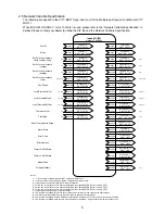
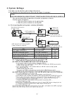
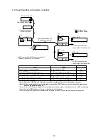
4-2 If used together with system controller.
(Note 1) When the LOSSNAY is interlocked, it should be configured from the shared system controller.
(Note 2) When changing the system configuration, such as the M-NET address, system controller being shared
must be registered or changed.
(Note 3) Refer to the “System Design and Construction Manual” for the outdoor unit for details on the M-NET wiring length.
(Note 4) Set the M-NET address so that it is not duplicated with other units.
(Note 5) When setting the shared system controller, configure LM ADAPTER as a system controller in each group.
SW1-2 [ON]
E
SW2-1 [ON]
Shielded wire ground
Centralized controller
(System controller)
Power supply unit
M-NET transmission line
(Centralized control line)
M-NET address 201 to 250 [factory setting 247]
(* Setting of position 100 not required.)
Factory setting
247
CN41
OFF
OFF
CN41
M-NET address of LM ADAPTER
LM ADAPTER power switch connector
Combined switch for LM ADAPTER / system controller
OC central control (SC) on/off switch
OC power supply connector
SWU2, 1 [201 to 250]
CN41 as is (power not supplied)
SW1 - 2 [ON] (Used together with system controller)
SW2 -1 [ON] (Central control)
CN41 as is (power not supplied)
Item
Setting
ON
OFF
1
2
3
4
5
6
7
8
9 10
ON
OFF
1
2
3
4
5
6
7
8
9 10
ON
OFF
1
2
3
4
5
6
7
8
9 10
SW2-1 [OFF]
as is
❇
OC : Outdoor Unit
: Switch Position
M-NET transmission line
(Indoor/outdoor transmission line)
M-NET transmission line
(Indoor/outdoor transmission line)
LM ADAPTER
TB2
CN41
CN41
TB7
TB3
TB7
TB3
OC
OC
as is
as is
CN41

