background image

Summary of Contents for LMAP04-E

Page 1: ... 4 3 Initialization Settings of LONWORKS Network 13 5 Confirming Operation 14 5 1 Flow of Onsite Adjustments 14 5 2 Preparation Material for Onsite Adjustments 14 5 3 Preparation and Setting 14 5 4 Test Run 15 6 Troubleshooting 16 6 1 Abstract 16 6 2 Troubleshooting 17 6 3 Error Code list 19 Appendix Test run check sheet 20 Before using the unit please read this Installation Manual carefully to en...

Page 2: ......

Page 3: ...fect connection and fixed may result in heating or fire Securely install the cover panel of the LM ADAPTER If the cover panel is not installed properly dust or water may enter the unit and fire or electric shock may result Never modify or repair the unit by yourself Any deficiency caused by your modification or repair may result in an electric shock or fire Consult with your distributor for repair...

Page 4: ...packaging bags so that children will not play with them If children play with a plastic bag which was not torn apart they face the risk of suffocation Be sure to shut off the power source of the unit and all the other unit to connected to the unit before wiring Doing so may cause an electric shock or a malfunction Use only an earth leakage breaker and fuse of the specified capacity If no earth lea...

Page 5: ...A TB1 Power supply terminal 2 ø4 5 hole TB2 M NET transmission terminal TB21 LONWORKS transmission terminal Unit mm in 10 7 5 5 16 ø10 ø13 32 4 5 3 16 9 6 3 8 59 6 2 3 8 340 13 7 16 325 12 13 16 60 2 3 8 240 9 1 2 360 14 3 16 2 ø3 16 hole 13 32 Item Power Source Current Consumption Dimensions Net Weight Operation Environment Installation Environment Description 220 240V 50 60 Hz 50 mA Maximum 340 ...

Page 6: ...Item Description FT3150 P20 10MHz Neuron CHIP FT X1 Free Topology 78kbps Network Transformer Performance 2 5 inputs second Average communication capacity 50 inputs second for one second Peak communication capacity CITY MULTI LOSSNAY OA Processing Units A control unit Mr Slim AK control unit Mr Slim K control unit Room air conditioner RAC Housing air conditioner HAC Air To Water Booster unit Air To...

Page 7: ... remote controller 4 For the use of this function turn ON the switch SW1 1 on LM ADAPTER Factory setting OFF 5 For the use of this function turn ON the switch SW1 8 on LM ADAPTER Factory setting OFF 6 For the use of this function turn ON the switch SW1 4 on LM ADAPTER Factory setting OFF 7 It is possible to use with other system controller 8 This function is available only for the conventional ind...

Page 8: ... refer to FT3120 FT3150 Smart Transceiver Data Book For reference Cable Types and Typical Parameters LONWORKS Network transmission wire Cable type Breaker for wiring Breaker for Current Leakage 3A 3A 30mA 0 1 sec or less Wire dia AWG Rloop Ω km C nF km Vprop of C Belden 85102 single twisted pair standed 19 29 unshielded 150 C Belden 8471 single twisted pair standed 19 29 unshielded 60 C Level IV 2...

Page 9: ...h installation space as shown in the Fig Install in an area capable of withstanding a 3 3 kg load The unit shall be also installed in vertical direction only indicated by arrow making on the cover as shown in the Fig Use M4 screws as shown in Fig below to fix the product To prevent the product from falling make sure to fix at four places UP Unit mm in 20 20 13 16 13 16 13 16 20 13 16 20 Installati...

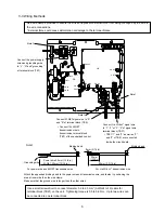
Page 10: ...N33 CNS3 CN605 CNL12 CN702 TB21 2 Connect LONWORKS signal wire to 1 2 or 3 4 of signal wire terminal block TB21 TB21 1 and 3 as well as 2 and 4 of TB21 are connected inside the circuit board Connect the power supply wires and grounding wire to L N and grounding of terminal block TB1 Connect M NET signal wire to A and B of terminal block TB2 Connect the M NET transmission wire to transmission termi...

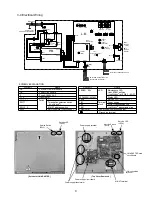
Page 11: ...ink Power supply 220 240V N 50 60Hz 3 4 Electrical Wiring Transformer Switch Function selection M NET address switch Termination selection switch LONWORKS SYMBOL EXPLANATION Power circuit board P B L B LM ADAPTER main board F SWU1 2 Service switch LONWORKS SWL Fuse AC250V 2A F NAME SYMBOL SW1 2 3 T1 2 SW71 LONWORKS transmission line Grounding terminal M NET transmission line Power source LED TB21 ...

Page 12: ...ion time switch OFF Before power supply ON OFF Connected cancellation command is transmitted to the indoor units None SW3 2 Initialization switch of air conditioner units OFF Always SW1 3 ON OFF Indoor temperature state interval switch Transmission interval 1minutes or more Transmission interval 10 minutes or more OFF SW1 2 ON OFF Used together with system controller switch used together with syst...

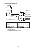
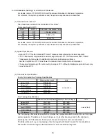
Page 13: ...t sequence LOSSNAY to the air conditioner Independent LOSSNAY Or when operation is to be controlled from LONWORKS BMS etc connected to the LOSSNAY remote controller LOSSNAY selection switch SW1 5 ON 2 When sequencing LOSSNAY to the air conditioner sequenced LOSSNAY and not controlling operation from LONWORKS BMS etc LOSSNAY selection switch SW1 5 OFF When sequencing LOSSNAY to the air conditioner ...

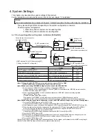
Page 14: ...tem controller Power supply unit M NET transmission line Centralized control line M NET address 201 to 250 factory setting 247 Setting of position 100 not required Factory setting 247 CN41 OFF OFF CN41 M NET address of LM ADAPTER LM ADAPTER power switch connector Combined switch for LM ADAPTER system controller OC central control SC on off switch OC power supply connector SWU2 1 201 to 250 CN41 as...

Page 15: ...500 1 640 500 1 640 450 1 476 The free topology transmission specification includes two components which must both be met for proper system operation The distance from each transceiver to all other transceiver and to the termination including the LPI 10 termination if used must not exceed maximum node to node distance If multiple paths exist e g a loop topology then the longest path should be used...

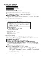
Page 16: ...1 Perform the previous operations described in Chapter 3 Installation Chapter 4 System Settings 2 If being used together with system controller perform the installation and electrical installation for system controller 3 Perform the initial processing for the LM ADAPTER Turn on the power supply for LM ADAPTER If being used together with system controller perform the initialization settings The ind...

Page 17: ... details of nv1n Reguest ON OFF refer to the following nv1n Request ON OFF command input This input network variable is used to allow On Request or Off Request of the indoor unit to be changed via the network When the ventilator LOSSNAY Interlocks with the indoor unit it becomes the same operation as the indoor unit Valid range SW1 7 OFF value field not used state field 0 indoor unit or ventilator...

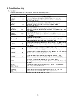
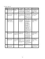
Page 18: ...unit is connected insert the jumper connector to CN41 If the power supply unit is not connected insert the jumper connector to CN40 SW71 LONWORKS The switch sets the termination of LONWORKS network According to the system design of LONWORKS network check whether it is properly set or not M NET Address switch SWU1 SWU2 If system controller is used check whether M NET address is overlapped or not In...

Page 19: ... LONWORKS network is not properly ended Refer to 2 1 Refer to 2 2 Refer to 2 3 Check for disconnection on TB21 short circuit and wire breakage on the network wire and so on Verify that the termination of LONWORKS network is properly set according to the system design Apply the binding again Even if it is operated with the remote controller system controller it is not informed to the host on LON si...

Page 20: ...ER is not completely initialized 2 Setting on M NET side is not properly completed 3 If system controller is used together LM ADAPTER is not registered to system controller 4 LONWORKS network transmission wire is not properly connected 5 The termination of LONWORKS network is not properly set 6 Binding of LONWORKS network is not properly ended Refer to 2 1 Refer to 2 2 Refer to 2 3 Refer to 4 4 Re...

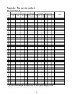
Page 21: ...T remote controller MA remote controller system controller M NET remote controller MA remote controller system controller M NET remote controller MA remote controller system controller or building control system M NET remote controller MA remote controller system controller M NET remote controller MA remote controller system controller M NET remote controller MA remote controller system controller...

Page 22: ...04 05 06 07 08 09 10 11 12 13 14 15 16 17 18 19 20 21 22 23 24 25 26 27 28 29 30 31 32 33 34 35 36 37 38 39 40 41 42 43 44 45 46 47 48 49 50 Check the building control system functions beforehand and check off each operation as it is tested For the check list you can either copy this sheet or make a new check list based on this sheet Unit address MEMO Test run of units SW1 9 Appendix Test run chec...

Page 23: ......

Page 24: ...LDG 2 7 3 MARUNOUCHI CHIYODA KU TOKYO 100 8310 JAPAN This product is designed and intended for use in the residential commercial and light industrial environment The product at hand is based on the following EU regulations Low Voltage Directive 2006 95 EC Electromagnetic Compatibility Directive 2004 108 EC Restriction of Hazardous Substances 2011 65 EC ...

Reviews: