3
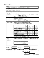
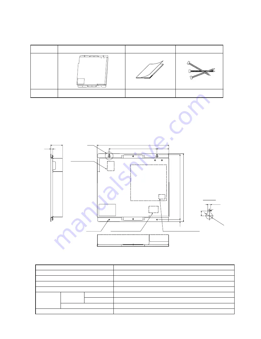
1. Parts Include
2. Specifications
Verify that the following parts are appended to the product.
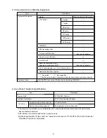
2-2 Environment Specifications
2-1 External View
Name
Shape
Quantity
Main Unit
Binding band
1
3
Installation manual
1
· The external interface file (XIF) is necessary for the product.
Upon verifying the 16-digit program ID (PID) which is bonded on the board, please contact your dealer.
R
Detail of A
A
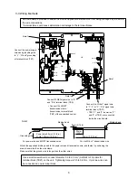
TB1
Power supply terminal
2-ø4.5 hole
TB2
M-NET transmission terminal
TB21
L
ON
W
ORKS
®
transmission terminal
Unit :
mm (in)
10
7.5
(5/16)
ø10(ø13/32)
4.5(3/16)
9.6
(3/8)
59.6(2 3/8)
340(13 7/16)
325(12 13/16)
60(2 3/8)
240(9 1/2)
360(14 3/16)
(2-ø3/16 hole)
(13/32)
Item
Power Source
Current Consumption
Dimensions
Net Weight
Operation
Environment
Installation Environment
Description
~ 220 - 240V (50 / 60 Hz)
50 mA (Maximum)
340 (H) x 360 (W) x 59.6 (D) mm / 13 7/16 (H) x 14 3/16 (W) x 2 3/8 (D) in
3.3 kg
Temperature
Operating Range
Storage Range
Humidity
In the metal control box
30% to 95% RH (No condensation)
-15 to 43˚C
-20 to 60˚C

