background image

Lossnay

LGH-150RVXT-E
LGH-200RVXT-E
LGH-250RVXT-E

Models:

1509876HC8401

Installation Instructions

Summary of Contents for Lossnay LGH-150RVXT-E

Page 1: ...Lossnay LGH 150RVXT E LGH 200RVXT E LGH 250RVXT E Models 1509876HC8401 Installation Instructions ...

Page 2: ...re it is highly humid like a bathroom or other wet place W FRXOG FDXVH HOHFWULF VKRFN RU SRZHU OHDNDJH Connect the product properly to ground Malfunctioning or power leaks can cause electrical VKRFN LULQJ ZRUN PXVW EH SHUIRUPHG E TXDOL HG professionals and be implemented safely and securely in accordance with the engineering standards and the extension wiring rules for electrical equipment Poor co...

Page 3: ...operation is stopped It is recommended to install an Electrically operated damper z When using the product in an environment where there is a ZLQGRZ RU RSHQLQJ QHDU WKH RXWGRRU ORXYUH ZKHUH LQVHFWV DUH OLNHO WR JDWKHU DURXQG WKH LQWHULRU RU H WHULRU OLJKW WDNH QRWH WKDW small insects may intrude into the product z Q D FROG ZHDWKHU DUHD RU RWKHUV GHZLQJ RU IUHH LQJ FRXOG RFFXU RQ WKH PDLQ XQLW ZKHU...

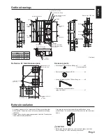
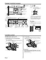
Page 4: ... LU VXSSO IDQ 2XWVLGH UHWXUQ DLU VXSSO DLU By pass damper plate By pass damper plate HLOLQJ VXVSHQVLRQ WXUH RYDO Power supply cable opening When using φ 250 duct Maintenance space 0RUH WKDQ Inspection opening 600 x 600 Maintenance cover IRU IDQ Maintenance cover for Cores LU OWHUV 150 to 250 317 1200 390 600 Reference for maintenance space FFHVVRU SDUWV DUH LQ WKH RVVQD XQLW 2 GXFW SODFH WRJHWKHU ...

Page 5: ...haust DLU RXWOHW OA outside DLU LQWDNH Lossnay unit Electrically operated damper Protection against the intrusion of cold DLU ZKLOH RVVQD LV VWRSSHG LQ ZLQWHU 7R EH SURYLGHG E WKH FXVWRPHU Q D UHJLRQ ZKHUH WKHUH LV ULVN RI IUHH LQJ LQ ZLQWHU LW LV UHFRPPHQGHG WR LQVWDOO DQ OHFWULFDOO RSHUDWHG GDPSHU RU WKH OLNH LQ RUGHU WR SUHYHQW WKH LQWUXVLRQ RI FROG outdoor air while Lossnay is stopped CAUTION ...

Page 6: ...USE TWO NUTS CAUTION KHQ RQ VLWH FRPPLVVLRQLQJ LV SODQQHG D VWUDLJKW GXFW length more than 10xD D duct diameter or equivalent from the source of turbulence like bends contractions and dampers etc to the measurement point is recommended for correct measurement In the United Kingdam on site measurment should therefore be measured in accordance with BSRIA guideline Commissioning Air System Applicatio...

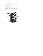
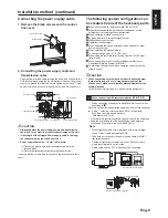
Page 7: ...DU DFFRUGLQJ WR the design of the system Perform electrical installation to meet local electrical regulations Always use double insulated PVC cable for the transmission cables LULQJ ZRUN PXVW EH SHUIRUPHG E TXDOL HG SURIHVVLRQDOV All supply circuits must be disconnected before obtaining access to the terminal devices TM1 LED3 6 6 6 6 TM3 TB5 TM2 TM4 ...

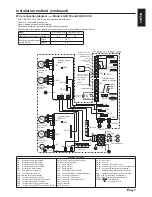
Page 8: ...KHUPLVWRU 5 1 RQQHFWRU 0RWRU IRU SDVV GDPSHU 1 RQQHFWRU DQ PRWRU 1 RQQHFWRU DQ PRWRU 1 RQQHFWRU DQ VSHHG 1 RQQHFWRU 1 RQQHFWRU CN19 Connector CN119 Connector CN20 Unused 1 RQQHFWRU 7KHUPLVWRU 2 CN26 Connector SDVV 9 DQ VSHHG FRQWURO 1 RQQHFWRU 5HPRWH FRQWURO VHOHFWLRQ 6 GGUHVV VHWWLQJ URWDU VZLWFK WHQV GLJLW 6 GGUHVV VHWWLQJ URWDU VZLWFK RQHV GLJLW LED1 to LED3 Inspection indicator lamp 3RZHU VXSS...

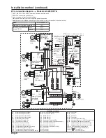
Page 9: ... 1 RQQHFWRU CN19 Connector CN119 Connector CN20 Unused CN21 Connector CN121 Connector 1 RQQHFWRU 7KHUPLVWRU 2 CN26 Connector SDVV 9 DQ VSHHG FRQWURO 1 RQQHFWRU 5HPRWH FRQWURO VHOHFWLRQ 6 GGUHVV VHWWLQJ URWDU VZLWFK WHQV GLJLW 6 GGUHVV VHWWLQJ URWDU VZLWFK RQHV GLJLW LED1 to LED3 Inspection indicator lamp 3RZHU VXSSO LQGLFDWRU ODPS SYMBOL Terminal block Connector on PCB 7 8 9 10 S A B 1 2 1 2 CN7 C...

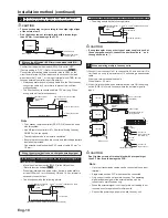
Page 10: ...nitor output 6 Operation monitor output When switching fan speed externally when a sensor or other GHYLFH LV FRQQHFWHG When switching By pass externally 9 To change fan speed by 0 10 VDC input 10 When using the remote local switching and the ON OFF input OHYHO VLJQDO 11 When connecting to the City Multi or Mitsubishi Electric Air RQGLWLRQHU 1HWZRUN 6 VWHP 0 16 12 To start stop Lossnay stand alone ...

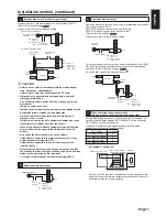
Page 11: ... SXOVH LQSXW VZLWFK 6 WR WKH 21 SRVLWLRQ 5HIHU WR IXQFWLRQ VHWWLQJV 1R KHQ LQWHUORFNLQJ ZLWK D SXOVH RXWSXW GHYLFH D SXOVH ZLGWK LV DW OHDVW P VHF WR WXUQ RVVQD 21 DQG VHF LQWHUYDO LV necessary to next output 7KH ZLULQJ VKRXOG EH WKH IROORZLQJ SLFWXUH Lossnay external control input 70 0 5 mm2 to 1 5 mm2 sheathed PVC cable External device 12 or 24 VDC Overall connection extension length ROORZ WKH R...

Page 12: ... Power Supply for heater Power Supply for relay TM3 TM3 4 0D 9 9 0LQ 9 P 9 P 0D 9 9 0LQ 9 P 9 P By pass operation indicator 9 8 7 10 2SHUDWLRQ PRQLWRU RXWSXW FDQ EH VHOHFWHG WR V PSDWKL H ZLWK H KDXVW fan or supply fan at SW 5 2 SW5 2 OFF Exhaust fan operation monitor output SW5 2 ON Supply fan operation monitor output 5HIHU WR IXQFWLRQ VHWWLQJV 1R Always check that it is the intended setting Oper...

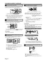
Page 13: ... 1 5HG Orange 3 Yellow 4 Green 5 HOORZ 9 UHHQ 20 Lossnay control board Lossnay control board Fan speed Ventilation mode selection Fan speed Ventilation mode selection External device Max wiring length 10 m Max wiring length 10 m 2QH VKLHOGHG ZLUH LV FRQQHFWHG WR WHUPLQDO 7 S on the PCB GGUHVV VHWWLQJ LV UHTXLUHG 5HIHU WR IXQFWLRQ VHWWLQJ VHFWLRQ M NET transmission cable Connect any of the City Mul...

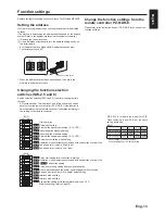
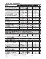
Page 14: ...ive pressure setting No 63 WHUQDO IDQ VSHHG LQSXW VHWWLQJ 9 No 51 Automatic ventilation mode setting 1R 2SHUDWLRQ PRQLWRU RXWSXW V QFKURQL HG ZLWK H KDXVW IDQ RU VXSSO IDQ No 61 DQ VSHHG IRU DLU YROXPH LJK LQSXW No 62 Fan speed for air volume Low input No 9 Delay start setting for air conditioner starting 1R 2SHUDWLRQ PRQLWRU RXWSXW V QFKURQL HG ZLWK H KDXVW IDQ RU VXSSO IDQ No 13 No 14 Exhaust fa...

Page 15: ...able 0 N A 39 7HPSHUDWXUH H FKDQJH HI FLHQF VHWWLQJ GLJLW Setting Data 0 to 9 GLJLW RI WHPSHUDWXUH H FKDQJH HI FLHQF WR N A 40 7HPSHUDWXUH H FKDQJH HI FLHQF VHWWLQJ GLJLW Setting Data 0 to 9 GLJLW RI WHPSHUDWXUH H FKDQJH HI FLHQF WR 0 N A 41 Outdoor temperature correction Setting Data 0 to 14 2XWGRRU WHPSHUDWXUH FRUUHFWLRQ Û WR Û N A 42 Indoor temperature correction Setting Data 0 to 14 5RRP WHPSH...

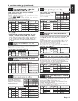
Page 16: ... fan speed Fan speed Display Exhaust fan Supply fan 1 down 2 down 4 4 3 2 3 3 2 1 2 2 1 1 1 1 1 1 1R Indoor positive pressure setting Supply fan speed becomes bigger than exhaust fan speed 5HPRWH FRQWUROOHU LQGLFDWHV IDQ speed of supply fan DIP SW Setting check 3 5 Setting check Down level of exhaust fan speed SW No Setting Function No Setting Data SW2 5 0 DFWRU VHWWLQJ DIP SW priority OFF DFWRU V...

Page 17: ...ce for TM2 DIP SW Setting check 3 5 Setting check Pulse input setting SW No Setting Function No Setting Data SW2 2 0 DFWRU VHWWLQJ DIP SW priority OFF DFWRU VHWWLQJ 1 NOT pulse input ON 2 Pulse input Function settings continued No 30 Night purge setting 1 Air volume 6HW IDQ VSHHG GXULQJ 1LJKW SXUJH 7R XVH 1LJKW SXUJH IXQFWLRQ LW LV necessary to set No 30 No 31 No 32 correctly This function is N A ...

Page 18: ...y Lossnay unit thermistor or not This function is N A from Lossnay unit DIP SW DIP SW Setting check 3 5 Setting check Indoor temperature display SW No Setting Function No Setting Data N A 0 DFWRU VHWWLQJ N A 1 Display on the screen of 3 5 1R Calculated supply air temperature display setting Set to display calculated supply air temperature or not This function is N A from Lossnay unit DIP SW DIP SW...

Page 19: ...n mode Either Yes or No Energy recovery ventilation mode By pass ventilation mode By pass ventilation mode Automatic Cooling Stop XWRPDWLF ROORZV WKH PDS Other than above Always energy recovery ventilation mode Function settings continued No 52 Automatic ventilation mode setting 1 Outdoor and indoor temperature gap 6HW RQH RI FRQGLWLRQV IRU SDVV PRGH LQ DXWR YHQWLODWLRQ RSHUDWLRQ temperature gap b...

Page 20: ...et by function No 52 Set by function No 54 Terget temp of air FRQGLWLRQHU Function settings continued Example 2 By pass Energy recovery ventilation map in automatic ventilation mode Function No Setting Data 52 Û 53 Û 54 Û When the setting of Function No 53 LV ORZ ZLWK XVLQJ WKH SUH KHDWHU IXQFWLRQ WKH RXWGRRU WHPSHUDWXUH PD EH GHWHFWHG DV higher and the mode may change to By pass mode even in wint...

Page 21: ...WHU VHOHFWLRQ REVHUYH WKH FDXWLRQV OLVWHG LQ 4 on the page 11 When set to auto ventilation mode while using the Pre heater IXQFWLRQ WKH RXWGRRU WHPSHUDWXUH PD EH GHWHFWHG DV KLJKHU DQG WKH PRGH PD FKDQJH WR SDVV PRGH HYHQ LQ ZLQWHU XULQJ SUH KHDWHU LV 21 RVVQD GRHV QRW JR WR DQ VSHHG YHQ UHPRWH FRQWUROOHU GLVSOD V DQ VSHHG RVVQD LV RSHUDWHG at Fan speed 2 Function settings continued No 59 Pre heat...

Page 22: ...ay operate at weaker fan speed Connection example if you use a CO2 VHQVRU ZKLFK 9 HTXDOV WR SSP 9 HTXDOV WR SSP 3DWWHUQ KHQ WKH LQSXW YROWDJH LV PRUH WKDQ 9 RVVQD RSHUDWHV DW IDQ VSHHG PD LPXP DLU YROXPH RZHU YROWDJH WKDQ 9 RVVQD RSHUDWH DW ZHDNHU IDQ VSHHG RQQHFWLRQ H DPSOH LI RX use a CO2 VHQVRU ZKLFK 9 HTXDOV WR SSP 9 HTXDOV WR SSP 3DWWHUQ Lossnay changes fan speed as the table below Connection...

Page 23: ...monitor output delay operation OFF ON TM380 Malfunction monitor output ON Error code 0900 appears on the remote controller KHFN HDFK IXQFWLRQ RSHUDWLQJ QRUPDOO 7XUQ WKH WULDO RSHUDWLRQ VZLWFK 3 6 6 2II Check points after installation work IWHU LQVWDOODWLRQ ZRUN SOHDVH GRXEOH FKHFN WKH SRLQWV EHORZ I WKHUH LV DQ WURXEOH LW PXVW EH GRQH FRUUHFWO KHFN SRLQWV 8QLW LQVWDOODWLRQ V WKH LQVXODWLRQ ZUDSSHG...

Page 24: ...SXW WHUPLQDO EORFN 70 In the case of voltage charged 12 or 24 VDC output device Connect to external control input terminals 1 and 2 In the case of uncharged a contact output device Connect to external control input terminals 1 and 3 Q WKH FDVH RI 0U 6OLP FRQWURO RU FRQWURO RQQHFW WR H WHUQDO FRQWURO LQSXW WHUPLQDOV 1 and 2 3HUIRUP WKH UHJLVWUDWLRQ RSHUDWLRQ XVLQJ WKH UHPRWH FRQWURO IRU WKH DLU FRQ...

Page 25: ...ctured by MITSUBISHI ELECTRIC CORPORATION TOKYO BLDG 2 7 3 MARUNOUCHI CHIYODA KU TOKYO 100 8310 JAPAN Importer in EU MITSUBISHI ELECTRIC EUROPE B V HARMAN HOUSE 1 GEORGE STREET UXBRIDGE MIDDLESEX UB8 1QQ U K ...

Reviews: