background image

130

5.4

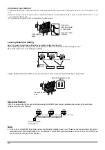
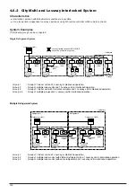
Multiple Lossnay Units in Interlocked Opera-
tion with One Indoor Unit. (M-NET only)

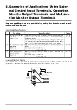
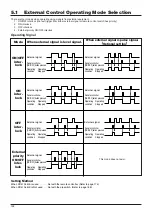
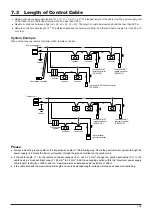
[Example: System 1]

Set the Main/Sub switch of the Lossnay connected to the M-NET transmission cable to “Main,” set the second and following
Lossnay units to “Sub,” and connect 

5

and 

6

of the Lossnay remote controller’s (PZ-41SLB-E) transmission cable terminal

(TM2) to the corresponding point on the next unit.

(One Point Advice)

Register the first Lossnay unit and the indoor unit to be interlocked.
It is not necessary to set the address or direct control for the second or following Lossnay units.
Malfunctions of the Lossnay units after the second unit will not appear on the remote controller.

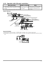
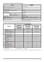
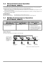
[Example: System 2]

Use the Lossnay remote controller to set the air conditioners and Lossnay units to separate groups.  Both interlocked operation
of an air conditioner and Lossnay units can be performed independently by connecting the remote display output for the indoor
unit and the external control input for the Lossnay unit.

(One Point Advice)

Do not register the indoor unit and Lossnay unit to be interlocked. In addition, ventilation switch on the MA remote controller will
be invalid, and the Lossnays’ error indicator will appear only on the Lossnay remote controller.

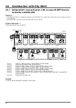
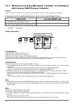
5.5

Interlocked Operation of Equipment such as the
Electrically Operated Damper and Booster Fan.
(M-NET only)

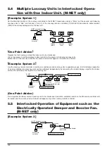
[Example: System 3]

Indoor unit

M-NET transmission cable

MA remote 
controller

Lossnay

(Main)

Lossnay

(Sub)

Lossnay

(Sub)

TM2

TM2

TM2

Lossnay remote controller
(PZ-52SF-E)

Indoor unit

M-NET 
transmission cable

Remote display output

External control input

MA remote 
controller

Lossnay

Lossnay

Lossnay

Lossnay

M-NET transmission cable

Indoor unit

MA remote 
controller

Operation moniter output

Electrically operated damper
Booster fan

Summary of Contents for Lossnay PZ-41SLB-E

Page 1: ...TECHNICAL MANUAL FOR CANADA Models Lossnay Unit LGH 50RX3 CAN LGH 100RX3 CAN LGH 200RX3 CAN Lossnay Remote Controller PZ 41SLB E PZ 52SF E ...

Page 2: ...mining Resistance of the Lossnay Core to Molds 29 6 Flame proofing Properties of Lossnay Core 31 7 Lossnay Core s Soundproofing Properties Test 33 8 Change in Lossnay Core Over Time 34 9 Comparison of Heat Recovery Techniques 36 CHAPTER 4 Characteristics 1 How to Read the Characteristic Curves 40 2 Calculating the Static Pressure Loss 40 3 How to Obtain Efficiency from Characteristic Curves 44 4 S...

Page 3: ...andards in Each Country 1 Ventilation Standards in Each Country 96 2 U S 97 3 U K 97 CHAPTER 11 Lossnay Q and A 100 Lossnay Remote Controller 1 Summary 107 2 Applicable Models 107 3 Terminology 108 4 System Features and Examples 109 5 Examples of Applications Using External Control Input Terminals Operation Monitor Output Terminals and Malfunction Monitor Output Terminals 127 6 Precautions When De...

Page 4: ...CHAPTER 1 Ventilation for Healthy Living Lossnay Unit ...

Page 5: ...nd schools with a total floor area of 3 000 m2 or more as buildings According to this law maintenance and management of the ventilation and water supply and discharge according to the Environmental Sanitation Management Standards is obligatory The following table gives a specific account of buildings in Tokyo Tokyo Food and Environment Guidance Center Report Specific Account of Buildings in Tokyo ...

Page 6: ...tion changes Approx 21 Standard atmosphere 20 5 Ventilation air volume standard will be a guideline where concentration does not decrease more than 0 5 from normal value The Building Standard Law of Japan 20 19 An oxygen deficiency of this amount does not directly endanger life in a normal air pressure but if there is a combustion device in the area the generation of CO will increase rapidly due t...

Page 7: ...tion when many people stay for long time 0 10 General tolerable concentration The Building Standard Law of Japan Law for Maintenance of Sanitation in Buildings 0 15 Tolerable concentration used for ventilation calculations 0 2 0 5 Observed as relatively poor 0 5 or more Observed as the poorest 0 5 Long term safety limits U S Labor Sanitation ACGIH regulation of laborer offices 2 Depth of breathing...

Page 8: ...dispersion of the stale air can be prevented by applying an entire negative pressure Design and construction properties An ideal design in which the supply air diffuser and exhaust air outlet position relation and air volume etc can be set freely is possible A system which adjusts the temperature and humidity of the supply air diffuser flow to the room environment can be incorporated The supply an...

Page 9: ...l to medium sized buildings with areas being ventilated using fresh outdoor air intakes formed of independent ventilation devices The rate of use of this method has recently increased as independent control is becoming ever more feasible Centralised ventilation method Independent zoned ventilation method Air intake fresh out door air Filters Air exhaust stale air Cassette type package air conditio...

Page 10: ... the equipment room The equipment can be inspected at any time Large as the entire system is affected Immediate inspection can be performed in the equipment room Fan power Installation space Zoning Designability Clarification of costs Controllability Comfort Maintenance and management Trouble correspondence Independent zoned ventilation method As the air transfer distance is short the fan power is...

Page 11: ...lown away The force that blows the paper away is called the wind pressure and this is normally expressed in units of Pa The wind pressure is divided into the following three types 4 2 1 Static pressure This is the force that presses the surroundings when the air is still such as in an automobile tyre or rubber balloon For example in a water gun the hydraulic pressure increases when pressed by a pi...

Page 12: ...e obtained Finally the throttle device is completely opened and the auxiliary fan is operated until the static pressure in the chamber reaches 0 The maximum point of the air volume point E the air volume at this point is called the fully opened air volume is obtained The points are connected as shown below and are expressed as air volume static pressure curves Q H curve Connection Wind dispersing ...

Page 13: ...r air intake volume per person table below iO Outdoor air enthalpy kJ kg iR Indoor enthalpy kJ kg Floor space per person table m2 According to the Japan Federation of Architects and Building Engineers Associations Required outdoor air intake volume per person table m3 h person Caution The application of this table to each type of room should be carefully considered in relation to the degree of smo...

Page 14: ... W m2 Indoor infiltration heat 47 6 W m2 Total 157 0 W m2 Conditions Middle floor of a general office building facing south Class Heat from walls qWS a Indoor infiltration heat Heat from glass from direct sunlight qGS from conduction convection qGS Accumulated heat load in walls qSS Generated heat from people Sensible heat qHS b Indoor generated heat Latent heat qHL Genarated heat from electrical ...

Page 15: ...value per person in office Sensible heat SH 63 0 W person Latent heat LH 69 0 W person Total heat TH 132 0 W person The heat generated per 1 m2 of floor space is heat generated from people 132 0 W person 0 2 person m2 26 4 W m2 2 Heat generated from electrical equipment lighting The approximate value of the room illuminance and power for lighting for a general office with illuminance of 300 350 Lu...

Page 16: ...it area When the outdoor air volume per person is 25 m3 h and the number of persons per 1 m2 is 0 2 persons the approximate heating load will be approximately 133 7 W m2 Outdoor air load Air conditions Standard design air conditions in Tokyo Type of load Load Outdoor air load 56 0 W m2 Internal heat 77 7 W m2 Total 133 7 W m2 Conditions Middle floor of a general office building facing south When t...

Page 17: ......

Page 18: ...CHAPTER 2 Lossnay Construction and Principle ...

Page 19: ...ucted of plates and fins made of treated paper The fresh air and exhaust air passages are totally separated allowing the fresh air to be introduced without mixing with the exhaust air Principle The Lossnay Core uses the heat transfer properties and moisture permeability of the treated paper Total heat sensible heat plus latent heat is transferred from the stale exhaust air to the fresh air being i...

Page 20: ...eaves in accordance with changing temperature rise or drop is called sensible heat The heat that enters and leaves due to the changes in a matter s physical properties evaporation condensation is called latent heat 1 Temperature sensible heat recovery 1 Heat conduction and heat passage is performed through a partition plate from the high temperature to low temperature side 2 As shown on the right ...

Page 21: ...volume are not equal the total heat recovery efficiency is low if the exhaust volume is lower and high if the exhaust volume is higher Refer to the Heat Recovery Efficiency Correction Curve in the applicable catalogue for more details SA Supply air Fresh cold or warm air RA Return air Stale cold or warm air Indoors Outdoors EA Exhaust air Stale air OA Outdoor air Fresh air Item Formula Temperature...

Page 22: ...rates from the wet bulb will balance at an equal state The temperature indicated at this time is called the wet bulb temperature 3 Absolute humidity x kg kg The weight kg of the water vapor that corresponds to the weight kg of the dry air in the humid air is called the absolute humidity 4 Relative humidity ϕ The ratio of the water vapor pressure Pw in the humid air and the water vapor pressure Pws...

Page 23: ...OA tOA tSA A S O R iRA iSA iOA tRA tRA S R A O tSA tOA XOA XSA XRA XRA XSA XOA iRA The quantity of heat recovered by using the Lossnay Core can be calculated with the following formula Total heat recovered qT γ Q iOA iSA W γ Q iOA iRA ηi Where γ Specific weight of air under standard conditions 1 2 kg m3 Q Treated air volume m3 h t Temperature C x Absolute humidity kg kg i Enthalpy kJ kg η Heat rec...

Page 24: ...CHAPTER 3 General Technical Considerations ...

Page 25: ...user enthalpy iSA 79 2 kJ kg from psychrometric chart Heat recovered 85 0 79 2 1 2 500 3 480 kJ kg 1 0kW Outdoor air load 79 2 53 2 1 2 500 15 600 kJ H 4 3 kW Calculated enthulpy recovery efficiency 3 480 3 480 15 600 100 18 2 Conventional ventilator If a conventional ventilator is used the heat recovered will be 0 as the supply air diffuser is equal to the outdoor air The outdoor air load is 85 0...

Page 26: ...diffuser enthalpy iSA 38 5 5 0 0 67 5 0 27 4 kJ kg Heat recovered 27 4 5 0 1 2 500 13 440 kJ h 3 7 kW Outdoor air load 38 5 27 4 1 2 500 6 660 kJ h 1 9 kW Sensible HRV Supply air diffuser temperature tSA 20 C 0 C 0 77 0 C 15 4 C Supply air diffuser enthalpy iSA 19 8 kJ kg from psychrometric chart Heat recovered 19 8 5 0 1 2 500 8 880 kJ h 2 5 kW Outdoor air load 38 5 19 8 1 2 500 11 200 kJ h 3 1 k...

Page 27: ...y 38 5 Indoor enthalpy 5 0 outdoor air enthalpy 85 Outdoor air enthalpy 85 outdoor air enthalpy kJ kg DA 0 67 enthalpy recovery efficiency 5 0 outdoor air enthalpy 53 2 indoor enthalpy 0 62 enthalpy recovery efficiency 27 4 65 3 Numerical value obtained Dry bulb temperature 14 6 C Wet bulb temperature 9 2 C Dry bulb temperature 27 89 C Wet bulb temperature 22 4 C from above equation and Relative h...

Page 28: ...87 Vapor pressure Pw kPa Absolute humidity x kg kg DA 50 49 48 47 46 45 44 43 42 40 41 39 38 37 36 35 34 33 32 30 31 29 28 27 26 25 24 23 22 20 21 19 18 17 16 15 14 13 12 10 11 9 8 7 6 5 4 3 2 0 1 2 3 4 9 10 0 75 0 76 0 77 0 78 0 79 0 80 0 81 0 82 0 83 0 84 0 85 0 86 0 87 0 88 0 89 0 90 0 91 7 8 5 6 1 1 8 1 9 2 0 5 5 6 0 6 5 7 0 2 2 2 1 2 3 2 4 2 5 7 5 8 0 2 6 2 7 8 5 9 0 2 8 2 9 9 5 1 0 0 1 0 5 1...

Page 29: ...ency cooling Enthalpy recovery efficiency heating 3 State of indoor blow air Season Winter heating Summer cooling Dry bulb Wet bulb Relative Absolute Enthalpy Dry bulb Wet bulb Relative Absolute Enthalpy Item temp temp humidity humidity i temp temp humidity humidity i DB C WB C RH kg kg kJ kg DB C WB C RH kg kg kJ kg Outdoors Indoors Heating Cooling Indoor temperature outdoor air temperature Outdo...

Page 30: ...cific gravity outdoor air volume Air specific gravity fresh air volume indoor enthalpy indoor blow enthalpy indoor blow enthalpy indoor enthalpy q1 q2 q1 q2 Heat recovery q3 or or Outdoor air load q1 Outdoor air load q1 enthalpy recovery efficiency enthalpy recovery efficiency Outdoor air load W Outdoor air load W Outdoor air load Outdoor air load with Lossnay Outdoor air load with Lossnay W W Hea...

Page 31: ...5 3 0 5 0 4 5 4 0 3 5 1 1 1 0 9 8 7 6 4 5 3 2 1 0 1 2 4 5 5 0 5 1 0 9 0 8 0 7 0 6 0 5 0 4 0 3 0 2 5 6 0 5 5 6 5 7 0 7 5 8 0 8 5 9 5 9 0 8 5 8 0 7 5 7 0 6 5 6 0 5 5 5 0 5 0 4 5 4 0 4 0 4 5 3 5 3 0 2 5 2 0 1 5 1 0 5 3 5 3 0 2 5 2 0 1 5 2 0 10 5 1 5 1 5 2 5 3 0 2 0 8 1 0 5 0 1 5 2 0 2 5 3 0 1 2 1 3 1 4 1 5 1 6 1 7 40000 40000 200 00 15 00 0 10 00 0 7 0 0 0 6 0 0 0 5 0 0 0 4 5 0 0 4 2 0 0 4 0 0 0 3 8 ...

Page 32: ...le size is 0 3 0 5 µm The air sampling tubes are installed at the each center of the locations of A B C D in the Lossnay inlet outlet ducts so that their openings are directly against the air flow and then connected to the impinger outside the duct The impinger is filled with 100 mL physiological salt solution The airborne bacteria in the duct air are sampled at the rate of 10L air minute for thre...

Page 33: ... the bacteria trapping filter since the particle size is small Cell diameter 0 5 µm Cell length 1 0 to 4 0 µm Both Bacillus subtilis and Pseudomonas diminuta are detected at the location A and B in the outlet side duct where they are sprayed but neither them are detected at location C in the air filtered by the HEPA filter and the location D in the air crossed in the Lossnay Core on the inlet side...

Page 34: ...name Brand Air filter Total heat recovery unit Lossnay ventilation fan B Specially treated paper Partition white Thickness 0 2 mm Filler block blue Thickness 0 2 mm Adhesive agent Vinyl acetate Specific gravity ratio 2 6 600 g m2 Residual Residual Carbonized Test No Test item flame dust area sec sec cm2 1 0 4 1 35 4 Vertical 2 min 2 0 7 7 38 2 heating Vertical 3 0 1 4 35 9 Horizontal 6 sec 1 0 0 2...

Page 35: ...Remarks Test results Class Direction No sec sec Horizontal cm Horizontal cm 1 0 0 8 2 4 7 18 7 7 3 Front Vertical 2 0 0 8 4 4 9 24 3 7 8 1 3 0 0 7 4 5 0 22 0 8 4 Evaluation The specimen conforms to Class 2 flame proofing heating time 3 min according to the Fire retardancy test methods of thin materials for construction as set forth by JIS A 1322 Material Testing Laboratory Persons in charge of tes...

Page 36: ...oncrete block with Cultures double faced mortar thickness 20 mm each specimen with a wood frame with inner dimension of installation 580 mm 190 mm 230 mm being installed method at The supply exhaust box and duct was test facility mounted in this and the main unit and weather cover was mounted Peripheral Oil clay was filled around the sound source sections Specimen configuration dimensions mm Refer...

Page 37: ...ed ventilation equipment 1 Air handling method 4 fan coil units perimeter zone per floor Chilling unit Absorption type 250 kT 1 unit turbo 250 kT 2 units Gas direct heating cooling boiler 340 kT heating 1630 kW 2 Ventilation method Air air total heat recovery unit Lossnay LS 200 18 units installed in penthouse Outdoor air treatment volume 46 231 CMH Exhaust air treatment volume 54 335 CMH 3 Lossna...

Page 38: ... and the measurement point was 200 m3 hr of this value 300 0 100 200 300 70 80 90 500 700 Characteristics in change of Lossnay Core over time 8 5 Conclusion 1 Changes in the characteristics of the Lossnay Core after approximately eleven years of use and an estimated 28 000 operation hours were not found In numerical values the static pressure loss was 150 to 160 Pa at 500 m3 hr which was a 10 Pa i...

Page 39: ...idity fresh air passes through the rotor with the heat and humidity being absorbed by the rotor As the rotor is rotating it moves into the exhaust air passage and the heat and humidity is discharged to outdoors because the exhaust is cool and has a low humidity The rotor rotates and returns to the fresh air passage to absorb the heat and humidity again Function of purge sector There are two separa...

Page 40: ...ng to combination Rotary type Heat accumulation humidity accumulation type counterflow The rotor core is composed of honeycomb shaped kraft paper etc to which a moisture absorbent is applied lithium chloride etc This rotor is rotated and heat accumulation humidity accumulation heat discharge humidity discharge of total heat exchange is performed by passing the exhaust and intake airs into a honeyc...

Page 41: ......

Page 42: ...CHAPTER 4 Characteristics ...

Page 43: ...e increases the air volume will decrease The air volume static pressure curve Q H curve shows this percentage A static pressure of 19 6 Pa is applied on to point A and the air volume is 500 m3 h The duct resistivity curve shows how the static pressure is applied when a duct is connected to the Lossnay Thus the L 9 97 m duct resistivity curve in the diagram is the curve that shows how the static pr...

Page 44: ... 20 21 2 1 2 0 1 9 1 8 1 7 16 15 14 13 12 11 10 9 8 7 6 22 23 24 25 5 4 3 2 1 100 200 400 600 800 1 000 2 000 4 000 6 000 8 000 10 000 20 000 40 000 60 000 80 000 100 000 200 000 400 000 600 000 800 000 1 00 0000 9 8 7 6 5 18 16 14 12 10 25 20 35 30 45 40 250 200 350 300 90 80 70 60 50 180 160 140 120 d 100cm d 400cm d 500cm 2 0 3 10 20 30 40 50 100 200 4 5 6 7 8 9 1 0 1 5 2 0 2 5 3 0 4 0 6 7 8 9 ...

Page 45: ...s shown using the following formula Duct inner surface Example Average velocity m sec 5 10 15 20 Very rough surface Concrete finish 1 7 1 8 1 85 1 9 Rough Mortar finish 1 3 1 35 1 35 1 37 Very smooth Drawn steel pipe Vinyl pipe 0 92 0 85 0 82 0 8 Circular pipe section pressure loss p λ v2 Pa p C v2 Pa 0 6 C v2 λ Friction resistance coefficient smooth pipe 0 025 C Local loss coefficient refer to Ta...

Page 46: ...each duct section Length of equivalent circular pipe No of vanes With or without vanes rectangular or circular 1 2 times value for similar 90 Length of equivalent circular pipe Free are ratio 14 or less D Duct No section Outline diagram Conditions C value R D 0 5 0 73 43D 90 0 75 0 38 23D 1 Smooth 1 0 0 26 15D Elbow 1 5 0 17 10D 2 0 0 15 9D W D R D 0 5 1 30 79D 0 5 0 75 0 47 29D Rectangular 1 0 0 ...

Page 47: ...40 Efficiency obtained from supply side air volume Heat recovery efficiency Air volume ratio Exhaust air volume Supply air volume Corrected heat recovery efficiency Recovery efficiency Static pressure outside unit Temperature recovery efficiency Enthalpy recovery efficiency heating Enthalpy recovery efficiency cooling Static pressure loss related parts straight pipe equivalent length total Pipe le...

Page 48: ...d that can be felt that is equivalent to a 1 000 Hz sound is obtained for each frequency The point where these points cross is the sound level curve and a sound pressure level numerical value of 1 000 Hz is expressed These are called units of phons For example the point on the 60 curve is perceived as 60 phons On average the human senses a sound that is less than 1 000 Hz as rather weak and a soun...

Page 49: ...g to the frequency However the sound generated from a vibration is not limited to one frequency but instead various frequencies are generated at differing levels This is expressed by the NC curve which is determined according to the difficulty of hearing a conversation Even if the sound is a very low level it is annoying if a specific frequency is emitted very loudly These sounds are suppressed to...

Page 50: ...n front of you overhead tracks is not possible 80 Conversation is not Train passing through possible unless voice is shopping district raised 70 Voice is raised Shopping district with intentionally to converse heavy traffic 60 Loud but normal In busy office conversation is possible 50 Sound is always audible Among quiet group and is disturbing of pedestrians 40 Quiet but not relaxing In quiet grou...

Page 51: ...iling embedded type Lossnay is the direct sound from the supply air diffuser return grille and is the echo sound to is the direct sound that is emitted from the main unit and duct and passes through the finished ceiling and leaks is the echo sound of 3 Setting of noise The following formula is used to obtain the noise value at a position in the room SPL dB PWL 10 log II i ii SPL Sound pressure lev...

Page 52: ...ion when disturbing noise may be emitted from large units Refer to Fig 4 a Sudden contraction of duct diameter Ex ø 250 ø 150 ø 200 ø 100 b Sudden curves in aluminum flexible ducts etc Especially right after unit outlet c Opening in ceiling plates d Suspension on weak material B The following countermeasures should be taken Refer to Fig 5 a Use ceiling material with high soundproofing properties h...

Page 53: ... length is the same a silencer duct with the small diameter is more effective 3 When supply air diffuser and return grille is sound source part 2 A If the main unit and supply air diffuser and return grille are integrated as shown in Fig 8 or if the measures taken in 2 a and b are inadequate the interior material in the room can be changed to that having a high sound absorbency as shown in Fig 8 a...

Page 54: ...35 30 25 20 15 10 62 5 125 250 500 1000 2000 4000 8000 Overall Octave band frequency near center Hz Octave band sound pressure level dB Low High Extra high Low High Extra high 1 5 m below Measurement point 1 5 m below Measurement point LGH 100RX type Background noise 25 dB or less A range Background noise 25 dB or less A range Measurement site Anechoic chamber Measurement site Anechoic chamber Ope...

Page 55: ...52 CHAPTER 4 Characteristics 6 List of Models 6 1 Model specifications and list of material colours for Industrial Lossnay ...

Page 56: ...53 CHAPTER 4 Characteristics ...

Page 57: ...54 CHAPTER 4 Characteristics ...

Page 58: ...on cable 1 IB 1 IM 1 Mounting screws 18 Duct connection flange 4 double flanges at SA and EA sides Protective cover 1 For installing upside down Lossnay connection cable 1 IB 1 IM 1 Duct packaging site EA RA OA SA EA RA OA SA EA RA OA SA Top view There is a space between the EA side and the OA side Top view One is inserted at each opening in the opposite direction Top view 2 are inserted on top of...

Page 59: ......

Page 60: ...CHAPTER 5 System Design Recommendations ...

Page 61: ...at point C shifts to the point C 1 2 Use in high humidity conditions Relative humidity 80 or more When using the system in high humidity conditions such as heated pools bathrooms mushroom cultivation houses high fog areas etc moisture will condense inside the Core and drainage will occur In these cases the general purpose Lossnay that uses treated paper cannot be used 1 3 Use in other special cond...

Page 62: ...take and exhaust of the Lossnay to clean the air and to prevent the Core from clogging Always mount this filter and periodically service it 4 Duct Construction Always treat the two ducts on the outdoor side outdoor air intake and exhaust outlet with insulation to prevent frosting or condensition The outdoor duct gradient must be 1 30 or more to wall side to prevent rain water from infiltrating the...

Page 63: ...35 1 0 2 9 1 000 Ethyl acetate 1 0 25 0 55 2 2 400 alcohol Ammonia 1 0 70 2 2 9 50 Hydrogen sulfide 1 0 15 0 44 2 9 10 Carbon monoxide 1 0 71 2 0 7 1 0 Carbon dioxide 1 0 44 500 1 400 1 8 Smoke 1 0 1 2 Formaldehyde 1 0 0 5 0 01 2 0 08 Sulfur hexaflouride 1 0 27 1 0 56 2 1 Skatole 1 0 27 1 0 56 2 0 Indole 1 0 27 1 0 56 2 0 Toluene 1 0 6 1 0 14 2 3 Measurement method Chemical analysis with colorimet...

Page 64: ...ound Soluble 1 000 Ketone Vapor Found Soluble 1 000 Skatole C9H9N Gas Bad odor Minute Toilet Indole C9H7N Gas Bad odor Minute Ammonia NH3 Gas Bad odor 635 40 50 Nitric monoxide NO 0 0043 50 Others Ozone O3 0 00139 0 1 Methane CH4 0 0301 Chlorine Cl2 Minute 0 5 Air Mixed gases Gas None 0 0167 Air Oxygen O2 Gas None 0 0283 reference Nitrogen N2 Gas None 0 0143 Carbon monoxide CO Gas Found 0 0214 Car...

Page 65: ...By pass ventilation will draw in the cooler outside air and reduce the cooling load on the system 2 Cooling using outdoor air During cooler seasons such as between spring and summer or between summer and fall if the people in a room cause the temperature of the room to rise By pass ventilation draw in the cool outside air and use it as is to cool the room 3 Night purge By pass ventilation can be u...

Page 66: ...ucting for vertical installation make sure that rain water will not enter the Lossnay unit from outdoors Always transport the unit in the specified state Vertical installation applies only to after installation and does not apply to transportation The motor may be damaged if the unit is transported vertically 9 3 Slanted installation Slanted installation is not possible Special note The LGH RX mod...

Page 67: ...o the airflow An example of such an installation is as shown below For such an installation care should be taken to avoid undue stress on the fan motors Referring to the diagrams below so long as Q1 Q2 there is no adverse effect on the motors This is generally such in the majority of cases Q H for Lossnay without extra fan Q H for Lossnay with extra fan Static pressure generating component Additio...

Page 68: ...CHAPTER 6 Examples of Lossnay Applications ...

Page 69: ... to 7th floor Offices salons board room Air conditioning Package air conditioning Ventilation Ceiling embedded type Lossnay straight centrifugal fan 1 2 Current topics 1 Operation system that answers individual needs is required Free independent operation system Simple control 2 Effective use of floor space elimination of machine room 3 Application to Building Management Laws Effective humidificat...

Page 70: ...ply air will be discharged into the ceiling where after mixing with the return air from the air conditioner it is supplied to the air conditioner The air in the toilet kitchenette and lift hall etc will be exhausted with a straight centrifugal fan in each room The OA supply for this section will use the air supplied from the Lossnay The OA volume will be obtained by setting the Lossnay supply fan ...

Page 71: ...floor air conditioner system layout Lossnay A Air cooling heat pump air conditioner B Air cooling heat pump air conditioner Additional room Additional room Women s dressing room Additional room Machine room Office machine room Men s dressing room Kitchenette Machine room Kitchenette Men s dressing room Office machine room Women s dressing room Additional room Machine room Office Office ...

Page 72: ...and thus the floor can be used to the maximum 5 Energy is conserved with the independent heat recovery 6 Fresh air air conditioning is possible with the independent system 2 Medium Size Office Building 2 1 System plan point In recent building air conditioning systems demands for a consistent rationalization from design through operation and control aspects are being made to meet diversified buildi...

Page 73: ...108 ø100 45 ø250 189 ø100 144 ø250 21 Air cooling heat pump chiller Air handling unit on each floor Floor type fan coil unit perimeter Air cooling heat pump chiller Ceiling embedded type fan coil unit Ceiling embedded type outdoor air treatment unit Air cooling heat pump chiller Single suction method Ceiling embedded type air cooling heat pump Package air conditioner City Multi Ceiling embedded ty...

Page 74: ...can cater for load fluctuations resulting from increases in office automation systems or changes in partitions hence requiting independent control of each module zone approx 70 m2 Outdoor Air Processing unit is used for ventilation and humidification and construction and space is reduced by using a system ceiling and ceiling chamber method Table 1 B system B Special floors City Multi and Outdoor A...

Page 75: ... be realised as work trends become more diversified Simultaneous cooling heating system due to necessity from increased fixed sash windows and increase in office automation systems Attention is being paid to building management methods which manage not only air conditioning systems for several buildings at one location but also manage other information ...

Page 76: ... the building is surrounded by other buildings the intake and exhaust ports must be separated as far as possible 3 Urban Small Scale Building 3 1 System plan points This system is based on effectively using available space within a limited area by installing the air conditioner and ventilator in available excess space For this application the air flow must be considered for the entire floor with t...

Page 77: ...lace and the air conditioned room is ventilated with the ceiling embedded type Lossnay The toilet and kitchenette etc are ventilated with a straight centrifugal fan Setting outline Building form RC Reinforced Concrete Total floor space 931 m2 GF to 2F Application per floor GF Waiting room diagnosis rooms surgery theatre director room kitchen 1F Patient rooms nurse station rehabilitation room cafet...

Page 78: ...e room Toilet kitchenette Straight centrifugal fan or duct ventilation fan Storage linen closet Positive pressure ventilation fan or duct ventilation fan The outdoor air is supplied from the hallway ceiling with the straight centrifugal fan and is distributed near the air conditioner after the air flow is reduced Kitchen Exhaust with negative pressure ventilation fan or straight centrifugal fan Ou...

Page 79: ...ilding and thus air conditioning and ventilation facilities are required This is also true for schools in polluted areas such as industrial districts At university facilities which have a centralised design to efficiently use land and to improve the building functions the room environment must also be maintained with air conditioning 5 2 Current system details and problem points 1 Mainly single du...

Page 80: ...nstallation on existing buildings must be possible 7 Installation and maintenance cost must be low 5 6 System trends 1 It is believed that environmental needs at schools will continue to progress towards high quality and various factors such as temperature humidity noise natural lighting and colour must be considered at the design stages Important topics are air conditioning ventilation and soundp...

Page 81: ...air conditioner Ventilation Ceiling embedded Lossnay 6 2 Conventional system and topics 1 Conventional systems have used centralised methods with air handling units and air conditioning and ventilation were generally performed together 2 Topics 1 Special knowledge is required for operation and there are problems in response to the users needs 2 When the centralised method is used the air even in r...

Page 82: ... is easy 2 Operation is possible according to each room s needs and is thus energy saving 3 Soundproof ventilation is possible with the separately installed ventilators 4 Energy saving ventilation is possible with the heat recovery ventilation 5 Space saving with the ceiling embedded type GF layout 1F layout Machine room Kitchenette Stairway Toilet Hall Foyer Study room Day care room FCU FCU FCU L...

Page 83: ......

Page 84: ...CHAPTER 7 Installation Considerations ...

Page 85: ...273 414 Duct ø 350 ordered by customer Duct ø 350 ordered by customer 414 Suspension bolt position Supply air grill Y pipe one direction falling pipe ordered by customer Supply air grill Suspension bolt position Maintenance space for element air filter and air supply fan Suspension bolt ordered by customer Inspection opening Duct downward slope 1 30 or more to wall side Rainwater entrance preventi...

Page 86: ...volume is required The positive and negative pressures of the room can also be adjusted with this LGH 50 100RX types LGH 200RX type 3 The units have a low noise design however for further noise reduction a silencer type supply return grille for supply return air in the room a silencer box for reducing the air sound into the room and a flexible silencer are available Exhaust air High and Extra High...

Page 87: ...h rain water 4 Use the optional parts control switch Ex PZ 41SLB etc for the RX type A centralised controller can also be used 1 3 Installation applications 1 Combined installation of two units The main unit s supply outlet and suction inlet and the room side and outdoor side positions cannot be changed However the unit can be turned over and installed as shown below This is applicable when instal...

Page 88: ...CHAPTER 8 Filtering for Freshness ...

Page 89: ... efficiency filters HEPA filter Coal dust Fry ashes Mud Sand Sprays Fluid particles Air filters Major particles Aerosol particle 0 001 0 01 0 1 0 3 1 10 100 1000 Table 2 Major dust concentrations Type Reference data Outdoor air floating dust Large city 0 1 0 15 mg m3 concentration Small city 0 1 mg m3 or less Industrial districts 0 2 mg m3 or more General office 10 mg h per person Indoor dust conc...

Page 90: ...lication JIS 14 types DOP 0 8 µm DOP 0 3 µm 82 8 12 5 9 2 5 99 65 60 25 Pre filter NP 400 EU3 3 Calculation Table for Dust Collection Efficiency of Each Lossnay Filter Model PZ 50RFM PZ 100RFM Dimension mm A 466 561 B 174 236 Number of filters perset 2 2 Note This is one set per main body 3 1 High Efficiency Filter Optional Parts A B 25 AIR FLOW PZ 50RFM 100 50 0 200 400 600 Pressure Loss Pa Air v...

Page 91: ...sed within the Lossnay units are shown below expressed in terms of collection ratio 20 40 60 80 100 Collection ratio High efficiency filter Colourimetric method 90 filter NP 400 0 2 0 3 0 4 0 6 0 8 1 0 2 0 3 0 4 0 6 0 8 0 10 0 20 30 40 60 80 100 Particle diameter µm ...

Page 92: ...oarse dust Cotton linter 5 filter and compare ASHRAE Degree of Degree of Comparison of Filter for air Colorimetric Atmospheric dust contamination of contamination of percentage of conditioning for fine method white filter paper white filter paper reduction in degree dust Electrostatic of contamination dust collector Air filter test for air Comparison of conditioning set by Degree of Degree of perc...

Page 93: ...on both filter papers is the same and the results are determined by the sampled air volume ratios on both sides Dust collection ratio Out flow side sampling amount In flow side sampling amount 100 Out flow side sampling amount Orifice Dust supply device Manometer Motor Dust container Mixing blades Dust supply outlet Unit mm Rectifying grid Air volume adjustment plate Air feed fan Window Specimen P...

Page 94: ... Qi 5 Calculation of Dust Concentration An air conditioning system using the Lossnay is shown below Using this diagram the level of dust concentration can be easily determined Dust concentration study diagram Qo Outdoor air intake amount m3 h Qi Indoor unit air volume Total air volume of indoor unit m3 h ηo Filtering efficiency of humidifier with high efficiency filter colorimetric method ηi Filte...

Page 95: ...2 60 2 040 m3 h Filtering efficiency of humidifier with high efficiency filter ηo 65 ηo 91 Particle diameter 2 1 µm Filtering efficiency of filter for inside unit ηi 65 ηi 57 Particle diameter 0 72 µm Outdoor air floating dust concentration Co 0 1 mg m3 Amount of dust generated in room G amount of dust generated per person no of persons in room 10 mg h person 20 persons 200 mg h If the inside dust...

Page 96: ...CHAPTER 9 Service Life and Maintenance ...

Page 97: ...itioner is used during a year 17 300 hours corresponds to about seven 7 years This explanation is not a guarantee of the service life of the product 2 Cleaning the Lossnay Core and Pre filter The Lossnay Core should be cleaned with a vacuum cleaner at least once every 2 years This will remove the dust that has accumulated at the surface and restore the functioning of the core to 98 to 100 of the o...

Page 98: ...CHAPTER 10 Ventilation Standards in Each Country ...

Page 99: ...pment 1 windowless rooms 2 rooms in theaters movie theaters assembly halls etc 3 kitchens bathrooms etc Rooms with equipment or devices using fire Offices where workers work Office sanitation regulated standards Impurity volume of less than 0 15 mg per 1 m3 of floating particles air Less than 10 ppm Less than 20 CO rate ppm when outside supply air has a CO rate of more than 10 ppm CO2 rate Less th...

Page 100: ... 8 l s m2 None Offices open plan 8 l s person 5 l s person 1 3 l s m2 Some Shops department stores and supermarkets 8 l s person 5 l s person 3 0 l s m2 Some Theatres 8 l s person 5 l s person Some Dance halls 12 l s person 8 l s person Some Hotel bedrooms 12 l s person 8 l s person 1 7 l s m2 Heavy Laboratories 12 l s person 8 l s person Some Offices private 12 l s person 8 l s person 1 3 l s m2 ...

Page 101: ......

Page 102: ...CHAPTER 11 Lossnay Q and A ...

Page 103: ... seen the phenomenon during heating in winter where the window pane is wet but the paper blinds are dry This is because the humidity is transferred through the paper membrane The Lossnay is kept dry by employing this same principle When a building is sealed and normal ventilation is used accurate exhaust is not possible unless a suction inlet is created The Lossnay has both an air supply fan and a...

Page 104: ...ation time Cooling 10 hours day 26 days month 4 months year operation ratio 0 7 Heating 10 hours day 26 days month 5 months year operation ratio 0 7 Power costs Tokyo Power special industrial power 6 kV supply Summer 16 15 kWh Other 14 65 kWh For an example if the total ventilation volume is 100 and the amount of odors generated from the toilet etc is 30 the total volume of conditioned air is stil...

Page 105: ...be avoided If the winter room air temperature is above 20 C along with the humidity above 50 and the outdoor temperature is 10 C or lower moisture condensation or frosting will occur on the Lossnay Core In this case the intake air must be preheated Plot the Lossnay intake side air conditions A and B on a psychrometric chart as shown below If the high temperature side air B intersects the saturatio...

Page 106: ...ct when the noise level is 100 dB A is approximately 30 dB A Ample filtering will not be possible with a saran net air filter Japanese domestic market model Same model as LGH 50RX type What is the short circulation 15 of the air intake exhaust air outlet 16 Is total operation possible with switches The Lossnay uses the forced simultaneous supply exhaust method so the insufficient ventilation found...

Page 107: ...ities 21 What are the anti vibration measures for the Lossnay 22 Can the LGH RX types be installed vertically Class 1 ventilation refers to mechanical ventilation forced simultaneous air supply exhaust using both intake and exhaust fans for suction feed All Lossnay models with built in air feed fans are Class 1 ventilators The ventilation method is classified in relation to the degree of natural a...

Page 108: ...Lossnay Remote Controller ...

Page 109: ......

Page 110: ...rom 1 to 15 Lossnay units together at the same time When using M NET transmission to operate from centralised control use the PZ 52SF E It can start and stop the unit change fan speed switch the ventilation mode It also includes indicators that show errors and when filter maintenance is required Refer to page 170 Lossnay M NET Remote Controller PZ 52SF E It can be used in combination with Mitsubis...

Page 111: ... It is compatible with 12V 24V DC or uncharged a contact signal Operation Mode This mode is used for selecting enabling disabling of the on off control signal from an external device and for setting inter locked operation of the external device and the Lossnay Please Refer to page 128 for details ON OFF interlock Enables both ON OFF and OFF ON external signals ON interlock Enables OFF ON external ...

Page 112: ... or other M NET controller Last touch priority Signal form 12VDC 24VDC uncharged a contact Ditto Uncharged a contact external monitor supply air fan monitor change Ditto ON OFF ON OFF and External priority ON OFF mode Delayed time can be varied only when the PZ 41SLB E is connected Return power automatic return is fixed when the PZ 41SLB E is connected Impossible when the PZ 41SLB E is connected U...

Page 113: ...Indoor unit MA remote controller Outdoor unit Indoor unit MA remote controller Lossnay Indoor unit MA remote controller Lossnay Indoor unit Indoor unit MA remote controller Indoor unit MA remote controller Lossnay Indoor unit MA remote controller Indoor unit MA remote controller Lossnay Indoor unit Indoor unit Group 1 Group 5 Group 3 Group 4 Group 2 Outdoor unit Outdoor unit Indoor unit MA remote ...

Page 114: ...en the address number has been changed the data in the memory is automatically reset Power suupy Power suupy Power suupy Power suupy Lossnay A C A C A C Remote controller PZ 41SLB E Air conditioning unit side remote controller Air conditioning unit side remote controller Air conditioning unit side remote controller Indoor unit 01 Centralised controller 201 Outdoor unit 51 Operation settings MA rem...

Page 115: ...n using A control remote controller Lossnay operation when indoor unit is stopped Lossnay stopping when indoor unit is operating Lossnay fan speed switching High Low Other common items Lossnay error indicator Ventilation mode Fixed to automatic Filter maintenance indicator Delayed operation External control operating mode selection Number of indoor units for interlocked group setting with one Loss...

Page 116: ...rol Mr Slim outdoor unit Mr Slim A control remote controller A control Mr Slim indoor unit Lossnay Lossnay M NET remote controller PZ 52SF E EXT signal source Lossnay M NET remote controller PZ 52SF E Remote controller Remote controller Lossnay Lossnay Lossnay M NET remote controller PZ 52SF E Lossnay Caution Lossnay remote controller PZ 41SLB E can not be used ...

Page 117: ... TEST TEMP TIMER SET CLOCK ON OFF LIMIT TEMP Without Lossnay interlock switches and indicators Remote controllers for Mr Slim indoor unit A control remote controller PAR 27AA ON OFF STAND BY DEFROST INDOOR UNIT ADDRESS NO ERROR CODE OA UNIT ADDRESS NO CENTRALLY CONTROLLED CLOCK ON OFF C 1Hr NOT AVAILABLE C CHECK MODE FILTER CHECK TEST RUN ON OFF CLOCK FILTER CHECK TEST RUN REMOTE CONTROLLER TEMP T...

Page 118: ...GH 50 100RX types 1 remote controller can operate from 1 to 15 Lossnay units For using LGH 200RX type 1 remote controller can operate from 1 to 7 Lossnay units Ordered part Remote controller PZ 41SLB E Also connect the power to the second and following Lossnay units Notes The maximum extension of the transmission cable is 500 m or less between Lossnay and remote controller switch between Lossnay a...

Page 119: ...ake the Main Sub setting when operating multiple Lossnay units When operating multiple Lossnay units set the first one to Main set the second and following to Sub Be sure the power is off when making the settings Change the Main Sub switch SW1 on the control board to Sub for the second and following Lossnay units Operation Method Up to 15 Lossnay units up to seven units when using LGH 200RX type c...

Page 120: ...ity to the last touch nected Lossnay Power supply Lossnay Power supply Transmission cable extension is 500 m or less PVC cable ø0 65 to 1 2 or strand wire 0 3 mm2 to 1 25 mm2 Remote controller PZ 41SLB E Transmission cable extension is 500 m or less PVC cable ø0 65 to 1 2 or strand wire 0 3 mm2 to 1 25 mm2 Lossnay up to 15 units or 7 units for LGH 200RX type Be sure to turn on the power for the se...

Page 121: ...e set to interlocked oper ation with 1 indoor unit Operation of Lossnay unit only When indoor unit is stopped Independent Lossnay unit start and stop When indoor unit is operating Delayed operation Optional setting Fan speed switching Ventilation mode Filter indicator Error Restrictions and precautions Details 1 unit 1 unit Possible Not possible 30 minute delayed operation when indoor unit cooling...

Page 122: ...y instructions Local permitted prohibited Status Operation Stop Fan speed switching Ventilation mode Error Error content Filter sign Local permitted prohibited Not used to the interlocked Lossnays Monitoring Operation Switched and display Group only or function available Not available For details on using the MA remote controller to set the functions of the indoor unit in order to operate the mach...

Page 123: ... remote controller PZ 52SF E 107 157 Lossnay 007 Lossnay M NET remote controller PZ 52SF E Indoor unit 009 MA Remote controller Group7 Indoor unit 011 Indoor unit 012 MA Remote controller Group9 Indoor unit 016 MA Remote controller Outdoor unit 059 Group 1 Group of 1 Lossnay unit and 1 Lossnay M NET remote controller Group 2 Group without Lossnay M NET remote controller Group 3 Group of multiple L...

Page 124: ...snay M NET remote controller PZ 52SF E 1 Group 16 Units No of controllable Groups Units Local Remote Model MELANS Series Start Stop Fan speed switching Ventilation mode switching Priority instructions Local permitted prohibited Status Operation Stop Fan speed switching Ventilation mode Error Error content Filter sign Local permitted prohibited Weekly Stop Starts per day Stop Starts per week Minimu...

Page 125: ...rigerants System Group1 Lossnay 004 Group3 Lossnay 008 Lossnay 002 Indoor unit 001 MA Remote controller Group2 Indoor unit 003 Indoor unit 005 Indoor unit 007 MA Remote controller Indoor unit 006 MA Remote controller Outdoor unit 051 Outdoor unit 055 address Refrigerant 1 Refrigerant 2 Group 1 Group of 1 indoor unit and 1 Lossnay in interlocked operation Group 2 Group of multiple indoor units and ...

Page 126: ...is started High Low Fixed to high Fixed to automatic 3000 hours 1500 hours 4500 hours No display Display Lossnays cannot be interlocked to the indoor units using K transmission converter MA remote controller PAR 20MAA Automatic 2 10 ME remote controller PAR F27MEA Automatic Dayly 2 10 Lossnay M NET remote controller PZ 52SF E Local Remote Model Start Stop Fan speed switching Ventilation mode switc...

Page 127: ...door unit from the air conditioner remote controller is possible and can switch between High Low Off From the air conditioner remote controller it is possible to switch the Lossnay only between High Low Off From the Lossnay remote controller it is possible to switch the Lossnay between High Low Off 2 When the 2 or more indoor units with different group are set for interlocked operation the Lossnay...

Page 128: ...ossnay 006 Lossnay 007 Lossnay 008 Indoor unit 009 Indoor unit 012 Indoor unit 016 Group 1 Group of 1 Lossnay unit and 1 Lossnay M NET remote controller Group 2 Group with no Lossnay M NET remote controller Group 3 Group of multiple Lossnay units and 1 Lossnay M NET remote controller Group 4 Group of 1 Lossnay unit and 2 Lossnay M NET remote controllers Group 5 Group of multiple Lossnay units and ...

Page 129: ...e materials regarding the LONWORKS compatible adaptor Table of Functions System Example Using M NET Lossnay Lossnay Building management system LMAP02 E Lossnay M NET remote controller PZ 52SF E Lossnay M NET remote controller PZ 52SF E M NET LONWORKS M NET Lossnay Lossnay LMAP02 E Lossnay M NET remote controller PZ 52SF E Lossnay M NET remote controller PZ 52SF E Connect the M NET transmission cab...

Page 130: ...al Both voltage and no votage signals are compatible with pulse input Set DIP switch 2 2 to ON A pulse signal duration of 200 ms or more is needed Output terminal during Lossnay unit operation uncharged a contact signal output Contact point rating 2A 240V AC Within 2A 24V DC Output terminal during Lossnay unit malfunction uncharged a contact sig nal output Contact point rating 1A 240V AC Within 1A...

Page 131: ...ressed Operating condition Operating Stopped External signal Remote controller ON OFF button pressed Operating condition Operating Stopped External signal Remote controller ON OFF button pressed Operating condition External signal Remote controller ON OFF button pressed Operating condition External signal Remote controller ON OFF button pressed Operating condition Operating Stopped Operating Stopp...

Page 132: ...only for 30 minutes Refer to page 167 5 3 Multiple External device Operation PZ 41SLB E M NET System Example When the Operation Signal is a Uncharged a contact Level Signal When there are multiple air conditioners or other external devices Characteristics Ordered parts Notes Lossnay operates when any of the external devices operate Remote controller External signals that can be received are listed...

Page 133: ...oups Both interlocked operation of an air conditioner and Lossnay units can be performed independently by connecting the remote display output for the indoor unit and the external control input for the Lossnay unit One Point Advice Do not register the indoor unit and Lossnay unit to be interlocked In addition ventilation switch on the MA remote controller will be invalid and the Lossnays error ind...

Page 134: ... and 2 Non polar External device 1 2 3 TM2 0 5mm2 to 1mm2 sheathed PVC cable TM2 Lossnay External control input External device 0 5mm2 to 1mm2 sheathed PVC cable No more than 500 m 1 2 3 If an optocoupler or any other type of polar coupler is used at the uncharged a contact connect the to 3 and the to 1 2 Using a 12V DC or 24V DC voltage sig nal 3 Uncharged a con tact External device Power Externa...

Page 135: ...necessary for connection Connection Method CO2 sensor etc when CO2 increases close Remote ON OFF adaptor PAC SE55RA E sold separately Lossnay control board Switch1 Orange 1 Red 2 Brown 3 High Low change CN16 Securely break off so as not to use Wiring length maximum 10 m Switch 1 High operation switch when closed High operation CO2 sensor etc when CO2 increases close Remote ON OFF adaptor PAC SE55R...

Page 136: ...X Y X Y Remote control circuit Relay circuit Relay power Switch 1 When on can not use the local remote controller PZ 52SF E to turn ON OFF When using PZ 41SLB E Remote Local changing is impossible Switch 2 When Switch 1 is ON you can turn Switch 2 ON to operate the Lossnay or turn Switch 2 to OFF to turn off the Lossnay Switch 1 Remote Local change switch Switch 2 ON OFF switch X Y Relay Contact r...

Page 137: ...tral system The indoor unit system Central controller transmission cable Indoor unit transmission cable Power supply unit Outdoor unit Indoor unit Lossnay Lossnay TB7 TB3 MA remote controller Lossnay remote controller PZ 52SF E Centralised controller Transmission cable Power supply unit PAC SC34KUA Lossnay M NET remote controller PZ 52SF E Lossnay M NET remote controller PZ 52SF E Lossnay Lossnay ...

Page 138: ...oller Lossnay remote controller Lossnay unit Lossnay remote controller Lossnay unit Lossnay remote controller Lossnay unit Lossnay remote controller Lossnay unit Lossnay remote controller Lossnay unit Transmission booster Lossnay remote controller ADDITIONAL INDOOR UNIT SIDE OUTDOOR UNIT SIDE Lossnay unit Lossnay remote controller Lossnay unit Lossnay remote controller Lossnay unit S TB2 Ground Gr...

Page 139: ...onnecting multiple indoor units and Lossnay units to an outdoor unit Indoor units Remote controllers Simple remote controllers Lossnay M NET remote controllers 35 MA remote controllers and Lossnay unit s are Not counted Centralised controller Transmission cable Power supply unit Lossnay M NET remote controller PZ 52SF E ME remote controller ME remote controller Indoor unit Indoor unit Indoor unit ...

Page 140: ...ble Routing this transmission cable with the transmission cable from another system on the same multi core cable will result in erroneous sending and receiving of signals which will cause misoperation Outdoor unit Indoor unit 2 core cable 2 core cable Multi core cable Indoor unit Lossnay Indoor unit Indoor unit Lossnay Indoor unit Indoor unit Lossnay Indoor unit Indoor unit Lossnay Outdoor unit Ou...

Page 141: ...tions as table 1 for more than 10 m Length Add any portion exceeding 10 m up to the longest permissible transmission cable length of 200 m Shielded sections shall have a cross sectional area of 1 25 mm2 to 2 00 mm2 Single refrigerant system Multi refrigerant system Transmission cable length Type of facility Electrical noise potential Type of facility Electrical noise potential Private residence or...

Page 142: ... Ground Centralised controller L4 T B 2 T B 3 Lossnay M NET remote controller PZ 52SF E Lossnay M NET remote controller PZ 52SF E Outdoor unit Indoor unit Lossnay Lossnay Lossnay Lossnay L2 L1 L3 Air conditioner remote controller Ground Transmission booster T B 2 T B 3 Please Always install the ground cable for the transmission cables in the following way Route the central control system through t...

Page 143: ...0 151 to 200 Branch controllers Minimum address of an outdoor unit 1 052 to 100 Central controller When the K control unit is in control 000 0 201 to 250 K transmission converter Minimum address of the K control type indoor unit 200 This cannot overlap with a system controller 201 to 250 013 015 016 010 014 005 006 007 004 003 002 001 101 105 106 107 103 051 213 Centralised controller 000 Power su...

Page 144: ...roller address is not registered H0 remains displayed and the system does not start up 7 No more than three Lossnay remote controllers can be set to the same group in a system using a central con troller Precautions 1 The maximum number of indoor units that can be interlocked is 16 Refer to page 123 2 1 Lossnay can be interlocked with an indoor unit Refer to page 123 3 Interlock settings 1 When a ...

Page 145: ...ng to the table below and automatic algorithm temperature maps Note that operation is fixed at heat recovery when the fan is stopped or when there is an abnormality with the thermistor Conditions Temperature Map When in automatic ventilation mode when not interlocked with City Multi or Mr Slim indoor unit Including when interlocked by external control input According to a When the outside temperat...

Page 146: ...20 15 10 5 0 5 10 15 20 25 30 35 40 45 TOA TRA 4deg 2deg d When there is a target temperature Cooling Or the outside temperature has been 28 C or higher in the last 24 hours when interlocked with Mr Slim and Mr Slim in ventilation mode Target temperature 8 C TOA Outdoor air temperature TRA Indoor air temperature The indoor air and outdoor air temperature are detected by the two temperature sensors...

Page 147: ...SSNAY delay OFF Purpose Heater cool down After system off Power source For damper LOSSNAY LGH RX type City Multi IC EA damper OA damper Relay OFF delay TIMER Switch or Thirmistor ON winter PAR F27MEA Pre heat unit M2 M1 S CAUTION All installation work should be carried out in accordance with local regulation Select and operate Pre heat unit that Lossnay supply intake air temperature becomes betwee...

Page 148: ...irregularly The Lossnay does not operate or operates irregularly Trouble Mode 4 Check with the remote controller checklist table 3 Check with the Lossnay checklist table 4 Precautions when diagnosing malfunctions When removing a transistor or printed circuit board make sure the breaker is thrown When removing the circuit board always hold it at both ends and remove carefully so as not to apply for...

Page 149: ...ssnay ventilation fixed Cancellation Cancellation Fan motor operation device error Damper motor error OA temperature sensor error RA temperature sensor error Test operation Dual address No ACK No response Controller communication error Communication circuit error Polarity not set PZ 41SLB E communica tion error Classification Communication error Measures taken by Lossnay Remote controller display ...

Page 150: ...t to Sub refer to page 164 11 When using M NET Is the address switch on the Lossnay circuit board SA1 SA2 set to the correct number refer to page 166 12 When using external control input Do the specifications of the external signal match specifications of signals that can be input to the Lossnay refer to page 163 13 When the external input signal is a pulse signal Is the pulse input switch SW2 2 o...

Page 151: ...n cable 3 Interlocked operation with external device does not occur The type of external signal does not match the connected terminal unit charged uncharged Mr Slim signal The type of external signal does not match the pulse input switch SW2 2 setting level signal pulse signal The external device signal is not being input The external device and signal cable wiring is longer than specifications 12...

Page 152: ...t It has been set for interlocked operation with the City Multi unit Cancel the interlocked operation setting refer to 15 Appendix 4 Cannot perform group settings for the Lossnay using MELANS ME remote controller or MA remote controller The remote controller shows 88 at the time of regis tration Power is not supplied to the Lossnay or power outside specifications is connected The M NET transmissio...

Page 153: ... LC 6608 displays on the remote controller and the Lossnay does not operate The remote controller is PZ 41LSB E and con nected to the TB5 A B Change to the PZ 52SF E remote controller PZ 41SLB E can not be used with a M NET system 10 The operation specified by the centralised con troller differs from the operation of the Lossnay The remote controller is PZ 41SLB E and con nected to the TM2 5 6 Cha...

Page 154: ...tor operation device error Lossnay fan will not stop Replace the table LC 3602 SLC 3602 3 blinks Damper related error Damper board operation is not cor rect Connectors for the damper unit are not correctly connected Remove the load and check or move the damper board by hand Check the connection of the lead wire s connectors and the circuit connector LC 5101 SLC 5101 4 blinks OA thermis tor related...

Page 155: ...ctors and the circuit connector 5102 5 blinks RA thermis tor related error Connectors for the thermistor are not correctly connected Check the connection of the lead wires connectors and the circuit connector 6602 6603 6604 1 5 blinks Communi cation cir cuit sec tion error Error with transmission cable Controller where error originally occurred is defective Lossnay board is defective Check transmi...

Page 156: ... release of the Delay Start button or the Fil ter Reset button is not good Replace the remote control Replace the remote control 4 Cannot stop the Lossnay with the remote controller display shows Interlocked External priority ON OFF setting is made Check the interlocked operation mode setting refer to page 171 5 Cannot switch fan speed with the remote con troller High Low change input CN16 is ON T...

Page 157: ... the power supply unit longer than 500 m between ends 3 Cannot register the Loss nay from the remote con troller or the controller Power supply to the Lossnay is not turned on Lossnay is connected to a power supply with a rating outside specification Transmission cable to the Lossnay is not con nected Lossnay transmission cable connection termi nal is wrong Lossnay address is wrong The length of w...

Page 158: ... connected terminal unit charged uncharged Mr Slim signal The type of external signal does not match the pulse input switch SW2 2 setting level sig nal pulse signal The external device signal is not being input The external device and signal cable wiring is longer than specifications 12V DC 24V DC Longer than limitations of external device Uncharged a contact Longer than 500 m Mr Slim signal Longe...

Page 159: ...ned ON When using the remote controller to change ventilation mode there may be a delayed start of up to 30 seconds depending on the timing Check the outdoor air temperature Remove the load and check or move the damper board by hand Check the connections of the lead wire connectors and the cir cuit connectors Check the connections of the lead wire connectors and the control circuit connectors Chec...

Page 160: ...10 8 84 25 5 00 40 2 96 19 30 92 4 15 74 11 8 49 26 4 82 41 2 86 18 29 50 3 15 08 12 8 17 27 4 65 42 2 77 17 28 14 2 14 45 13 7 85 28 4 49 43 2 68 16 26 87 1 13 86 14 7 55 29 4 33 44 2 59 15 25 65 0 13 29 15 7 27 30 4 18 45 2 51 14 24 51 1 12 74 16 6 99 31 4 03 46 2 43 13 23 42 2 12 22 17 6 73 32 3 89 47 2 35 12 22 39 3 11 72 18 6 48 33 3 76 48 2 28 11 21 41 4 11 25 19 6 24 34 3 63 49 2 21 10 20 4...

Page 161: ...it 208 V 230 V AC 5 V DC 12 V DC Transformer output 11 V to 20 V AC GND LED4 red lit when power is supplied to circuit 12 V DC Thermistor outdoor air Thermistor return air Damper position detector during Lossnay ventilation 12 V DC during by pass ventilation 0 V LED6 red lit when power is supplied to M NET M NET transmission cable shielded M NET transmission cable PZ 52SF E MELANS power supply uni...

Page 162: ...sh SW5 SW2 SW1 SW5 SW2 LED4 12 1 2 Wire connection diagram Models LGH 50 and 100RX Connect the wires shown as dotted lines Be sure to connect the grounding wire Breaker should be provided by the customer Symbol explanation PZ 41SLB E and PZ 52SF E cannot be used simultaneously M1 Motor for exhaust fan M2 Motor for supply fan C Capacitor GM Motor for Bypass move ment LS Microswitch TH1 Thermistor f...

Page 163: ...ect the grounding wire Breaker should be provided by the customer 10 10 Invalid in EU 220V 60HZ 220 240V 50HZ POWER SUPPLY L N PE L N 5 6 S B A DC24V2A DC 5V100mA AC240V2A AC220V100mA MAX MIN Operationmonitoroutput DC24V1A DC 5V100mA AC240V1A AC220V100mA MAX MIN Malfunctionmonitoroutput M2 M1 7 8 9 3 1 S B A 6 5 4 1 3 2 2 3 1 4 5 6 A B S 9 8 7 M2 M1 Subordination Main Transmissiion cable Lossnay u...

Page 164: ... 2 Secure the power supply cable and transmission cables using the cord clamp Upon completion of the wiring connections replace the control box cover CAUTION Always separate the power supply cable and transmission cable by 5 cm or more to prevent malfunctioning of the unit If the length of the stripped power cables wires is too long the conductors may touch and cause shorting LGH 50 and 100RX type...

Page 165: ...cover Control box Protective cover Control box When installing upside down When installing upside down 4 Changing the switch for High and Extra High To increase the air volume change the switch from high to extra high The factory setting is High Can be switched for each supply and exhaust separate ly LGH 50 and 100RX types High and Extra High switch High E High High E High Exhaust air Supply air L...

Page 166: ...he lower circuit board Main circuit board CAUTION The connection may vary according to the output signal type of the external device When using Mr Slim air conditioner and A control Interlock operation of except Mr Slim A control unit is not possible Connect the interlocking cable connector side to CN2L on the circuit board for the indoor Mr Slim unit and connect the lead wire side to the 1 and 2 ...

Page 167: ...2 and from unit 2 to unit 3 and so on up to a maximum of 15 units 7 units for type 200 using a transmission cable PVC insu lated PVC jacketed and either between ø0 65 and ø1 2 or between 0 3 mm2 and 1 25 mm2 in cross section 2 Change the setting on the main sub switch SW1 on the second and subsequent Lossnay units to sub Note Up to four 0 3 mm2 stranded wires or ø0 65 PVC wires can be connected to...

Page 168: ...ieled wire is connected to the other shieled wire Terminal connection Address setting is required Refer to function setting section M NET transmission cable Connect any of the following City Multi indoor unit Lossnay remote controller PZ 52SF E or Mitsubishi Electric Air Conditioner Network System MELANS to the Lossnay Type Shielded wire CVVS CPEVS Wire diameter 1 25 mm2 to 2 0 mm2 Securely connec...

Page 169: ...ANS Power supply unit M NET transmission cable Lossnay M NET remote controller PZ 52SF E Lossnay 0 1 SA1 SA1 0 2 0 1 SA1 SA2 SA1 SA2 12 3 Function settings You must set the address when connecting to the City Multi Lossnay M NET remote controller PZ 52SF E and MELANS 12 3 1 Setting the address Use the following procedure when performing the address set ting for dedicated Lossnay The method to be e...

Page 170: ... 2 and 5 Perform the necessary function settings using the function selection switches SW 2 and 5 The setting can be changed at any time On the LGH 200RX type set both the upper and lower circuit boards similarly 1 Settings for pulse input Set as shown when connecting the pulse signal equipment from a building maintenance system to an external input 2 Setting for selection of fan speed method Set ...

Page 171: ...ould operate when external devices are started or stopped If the PZ 41SLB E is used set it at the remote control Refer to page 174 OFF ON Mode Units The Lossnay will start and stop in accordance with starting 7 ON OFF interlock and stopping of an external devices 8 Factory setting Subsequent operation will be possible using the remote controller for the Lossnay or MELANS 7 The Lossnay will operate...

Page 172: ...er to the installa tion instructions for the remote controller for the Lossnay or MELANS Check whether or not there is a power supply unit and that the power has been turned on On systems with only a Lossnay a power supply unit is required Check if the pulse input switch SW2 2 is off Check the overall length between the air conditioner or external device and Lossnay Refer to technical publications...

Page 173: ...ction occurs Ventilation Modes Indicates the ventilation mode status Heat recovery Heat exchange HEAT EX By pass BY PASS Automatic Heat ex By pass Power Display Displayed while the Lossnay remote controller is powered on CHECK Display Displayed together with the malfunctioning unit 3 digits and an error code 4 digits Delay time Display Displays delay time Delay setting SETTING XX MIN DELAYED XX 0 ...

Page 174: ...icates that the unit is operating in non auto matic bypass ventilation mode The above display indicates current operation with a gentle fan speed Operation lamp Operation lamp Delay time This setting is used to deter mine how long will elapse after the start of operation of the external device until the Lossnay unit begins to oper ate Interlocked mode This setting is used to deter mine the way in ...

Page 175: ...t be per formed using the remote controller The Lossnay unit stops operating in response to a signal or pulse which is input from a building management system or the like start ing of the Lossnay unit must be performed using the remote controller Same as for setting 1 above 13 3 Care and Upkeep A Ac ct ti io on ns s r re eq qu ui ir re ed d w wh he en n t th he e F Fi il lt te er r C Cl le ea an n...

Page 176: ...form insertion of a single unit switch box without a cover 2 Lay the wiring duct to the switch box 3 Connect the signal wires from the Lossnay unit to the switch box Note that 2 core telephone cable should be used furthermore this cable should be of PVC insulated PVC jacketed and either between ø0 65 and ø1 2 or between 0 3 mm2 and 1 25 mm2 in cross section 4 Use standard putty to create a secure ...

Page 177: ...ram Press the switch to change the setting in the repeating sequence factory setting 1 2 3 4 1 original setting at factory shipment When the button is released before 5 seconds have elapsed the display will turn off and the current setting will be selected Note that this value is set to 1 before ship ment from the manufacturing plant DELAY START FILTER 1 2 3 4 3 Connection of wiring and remote con...

Page 178: ...eration switch from the Lossnay unit s controll box is On If two or more Lossnay units are currently being used together this number will indicate that the correct set ting has not been performed using the units Main Sub switches If two remote controllers are currently being used together this number may indicate that one of these controllers is not connected If two remote controllers are used tog...

Page 179: ...cannot perform the function for the button that has been pressed This display flashes concurrently with the display of the unavailable function ON OFF Button Switches between run and stop The lamp on the button stays lit during operation Fan Speed Adjustment Button Used to select the fan speed of either Low or High FILTER Button Press two times to reset the filter sign display HEAT EX BY PASS AUTO...

Page 180: ...inal board while inserting the cable The cable connects to the main terminal board when it is inserted into the bot tom terminal When disconnecting the cable hold down the tab while pulling out the cable After inserting the cable slightly tug on it to check that it does not easily dis connect If the cable is not securely connected a short circuit or malfunction may occur 4 Remove the Lossnay M NET...

Page 181: ... a multi unit system Set the address according to its position in the system In addition refer to page 166 for more information concering the setting of the addresses 6 After setting the Lossnay M NET remote controller address attach the Lossnay M NET remote controller cover When attaching the Lossnay M NET remote controller cover set the top of the cover onto the two top hooks and then push in th...

Page 182: ...ay M NET remote controller After the button is pressed once the Lossnay M NET remote controller address and then the Lossnay unit address is dis played Afterwards each press of the button increase the Lossnay unit address by 1 as shown below Holding down the but ton changes the address more quickly 101 001 002 098 099 Set Lossnay M NET remote controller address Flashes 4 When the address of the Lo...

Page 183: ...leted to delete the regis tration of the Lossnay unit that is currently displayed FILTER When the display appears as shown above hold down ON OFF for 2 seconds each time If the registration is deleted correctly appears in the display If the registration is not deleted correctly flashes in the display Check that the select ed Lossnay unit addresses and the wiring are correct Note In the case of LGH...

Page 184: ... setting Current time display Group number display Display Operation condition display Remote operation prohibition permission display Operation mode display Fan speed display Ventilatior operation display External input condition display Filter sign display Timer operation display Function area G01 1F1ROOM OPERATION SETTING HEAT RECOVERY ON FAN REMOTE CONTROL PROHIBIT MON PROH COL M MR TIMER ON F...

Page 185: ... to 50 group numbers The switch can also display group names Ventilation off High Low FAN FAN HEAT RECOVERY Function The ON OFF condition of the displayed group is switched Used to the type of the operation mode selection The Fan speed can be selected as high or low The operation mode of the interlocked Lossnay unit can be performed Where there is no interlocked Lossnay unit the operation of this ...

Page 186: ...this controller are set according to the DIP switch settings Each switch is set to the OFF and ON positions as shown below The functions of this controller are selected by DIP switch The DIP switches are set to OFF when the controller is shipped from the factory DIP switch OFF ON 1 2 3 4 5 6 7 8 ON OFF User operation mode OFF Master system controller OFF No K transmission converter installed OFF O...

Page 187: ...o select 1 GROUP SETTING 1 GROUP SETTING ADDRESS UNIT REMOTE CONTROLLER SYSTEM CONTROLLER G01 The configuration setting screen is displayed 3 Press the button to display the group number to be set 4 Press the button to move the cursor to the address display position to be set 5 Use the numeric keypad to set the address of the indoor unit local remote controller and slave system controller in the d...

Page 188: ...h No 1 is set to ON at this time the initial setting menu screen is displayed without the initial setting screen 9 The user operation menu is displayed Once the group configuration settings are completed user operation can be performed Refer to Section 15 1 4 Interlocked Operation Setting when per forming interlock operation settings Additions Deleting all group configuration data Display G00 on t...

Page 189: ...he cover to ON Note Always uses the DIP switch No 1 to change the setting This operation will be invalid if performed on another screen 1 GROUP SETTING 2 INTERLOCKED SETTING 3 REFRIGERANT MONITOR 4 MALFUNCTION LOG MONITOR 5 USER SETTING MENU 2 The initial menu screen is displayed 3 Press the button to select 2 INTERLOCKED SETTING 2 INTERLOCKED SETTING UNIT ADDRESS INTERLOCKED UNIT ADDRESS 005 4 Th...

Page 190: ... interlocked Lossnay unit 8 Repeat operation 5 to 7 to set the indoor units in interlocked operation con trolled by this controller 9 When all settings are completed press the button BACK SCREEN 1 GROUP SETTING 2 INTERLOCKED SETTING 3 REFRIGERANT MONITOR 4 MALFUNCTION MONITOR 5 USER SETTING MENU Initial setting screen is displayed This ends the interlocked operation setting Return to where user op...

Page 191: ...d operation with a ventilation unit When changing Lossnay fan speed Press the Ventilation button C TIMER SET PAR 20MAA ON OFF CENTRALLY CONTROLLED ERROR CODE CLOCK ON OFF C CHECK CHECK MODE FILTER TEST RUN FUNCTION C 1Hr NOT AVAILABLE STAND BY DEFROST FILTER CHECK TEST TEMP B A C Ventilation Display Displayed during ventilation Lossnay operation Lossnay fan speed Low Lossnay fan speed High The set...

Page 192: ...unit is equipped with outdoor air intake 240 V 220 V 230 V Energy saving cycle automatically enabled Energy saving cycle automatically disabled 100 Hr 2500 Hr No filter sign indicator Quiet Standard High ceiling 4 directions 3 directions 2 directions Not supported Supported No vanes Equipped with vanes No 1 set Equipped with vanes No 2 set Disabled Enabled Not supported Supported NOTE When the ind...

Page 193: ...epeating steps and FUNCTION Mode No display When registered using the Mode selection button the registered indoor unit begins fan operation When you want to know the location of the indoor units of the unit address No whose functions were selected check here When the unit address No is 00 or AL all the indoor units of the selected refrigerant address perform the fan operation Ex When refrigerant a...

Page 194: ...pear 15 3 Network Remote Controller PAR F27MEA INDOOR UNIT ADDRESS NO INDOOR UNIT ADDRESS NO OA UNIT ADDRESS NO INDOOR UNIT ADDRESS NO OA UNIT ADDRESS NO Both INDOOR UNIT ADDRESS NO and OA UNIT ADDRESS NO will appear simultaneously E A B D H G C F PAR F27MEA ON OFF CENTRALLY CONTROLLED DAILY AUTO OFF REMAINDER ERROR CODE CLOCK ON OFF CHECK MODE FILTER TEST RUN 1Hr NOT AVAILABLE STAND BY DEFROST FI...

Page 195: ...tered units 6 Display the indoor unit address No at OA UNIT ADDRESS NO Press the Operation mode button shown as G and the following display will appear Press once again to return to INDOOR UNIT ADDRESS NO shown in Step 2 7 Use the and TIMER SET buttons shown as H to select the address of the indoor unit to be registered Select the indoor unit address number to be confirmed 8 Press the Timer contin...

Page 196: ...re displayed according to their address number with the indoor unit When the above is displayed press the Time conversion button shown as F twice If the transmission is faulty the properties will flash as Check the wiring and the address definitions and then do the above operation again B To return to the normal operation mode Press and hold down both the FILTER button shown as A and the Louver bu...

Page 197: ...MEMO ...

Page 198: ...Y04 002 Jul 2004 MEE ...

Reviews: