175
Inspection
number
0900
6608
4000
5101
5102
3602
BY-PASS
AUTO
HEAT EX.
Sequence
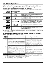
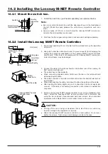
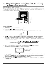
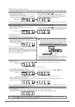
Initiate the supply of power to the Lossnay unit. (The [HO] display will
flash for approximately 40 seconds)
Press the ON/OFF button. The Operation lamp will turn on and the
Lossnay unit will begin to operate.
Press the Function selector button: Each time it is pressed, the corre-
sponding display will change in accordance with the sequence [HEAT
EX.] (non-automatic)
→
[BY-PASS] (non-automatic)
→
[AUTO].
Press the Fan Speed Adjustment button to toggle between Low and
High.
Press the Operation switch. The Operation lamp will turn off and the
Lossnay unit will stop operating.
13.7 Trial Operation
After installation has been completed, it is of the utmost impor-
tance that trial operation of the Lossnay unit and any external
device such as an air conditioner is carried out.
When power supply is supplied to the remote controller the [HO] display will flash (for approximately 40 seconds); following this,
the system will switch to operation-start mode.
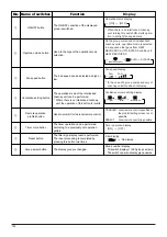
Relevant
button
1
2
3
4
5
Relevant display
items
●
Note that when the Ventilation Mode selector button is pressed, it will take up to 40 seconds before the operation of the
damper changes accordingly.
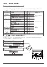
If an inspection number should be flashed, refer to the following
table and take the required action.
Cause
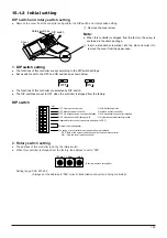
The SW2 trial-operation switch from the Lossnay
unit's controll box is On.
If two or more Lossnay units are currently being used
together, this number will indicate that the correct set-
ting has not been performed using the units' Main/Sub
switches.
If two remote controllers are currently being used
together, this number may indicate that one of these
controllers is not connected.
If two remote controllers are used together, this num-
ber may indicate that both of these controllers are not
set automatically when the power supply is turned on.
Multi-core cable has been used in place of a number
of signal wires.
A circuit abnormality has occurred in the Lossnay unit.
A breakdown has occurred in the Lossnay thermo (OA side).
A breakdown has occurred in the Lossnay thermo (RA side).
A breakdown has occurred in the damper motor.
Required action
Turn off the trial-operation switch. (refer to page 169)
Turn off the power supply and use the Main/Sub switches
to specify one Lossnay unit as the Main and the others as
Sub. Following this, turn the supply of power back on.
Note that all Lossnay units are specified as Main before
shipment from the manufacturing plant. (refer to page 164)
Turn off the power supply, connect the remote con-
troller, and turn the power supply back on.
(refer to page 174)
Turn off the power supply and turn the power supply
back on.
Switch back to the use of standard wiring and install
each signal wire separately.
Turn off the supply of power and contact the retail out-
let from where this product was purchased for further
instructions.
Summary of Contents for Lossnay PZ-41SLB-E
Page 4: ...CHAPTER 1 Ventilation for Healthy Living Lossnay Unit ...
Page 17: ......
Page 18: ...CHAPTER 2 Lossnay Construction and Principle ...
Page 24: ...CHAPTER 3 General Technical Considerations ...
Page 41: ......
Page 42: ...CHAPTER 4 Characteristics ...
Page 56: ...53 CHAPTER 4 Characteristics ...
Page 57: ...54 CHAPTER 4 Characteristics ...
Page 59: ......
Page 60: ...CHAPTER 5 System Design Recommendations ...
Page 68: ...CHAPTER 6 Examples of Lossnay Applications ...
Page 83: ......
Page 84: ...CHAPTER 7 Installation Considerations ...
Page 88: ...CHAPTER 8 Filtering for Freshness ...
Page 96: ...CHAPTER 9 Service Life and Maintenance ...
Page 98: ...CHAPTER 10 Ventilation Standards in Each Country ...
Page 101: ......
Page 102: ...CHAPTER 11 Lossnay Q and A ...
Page 108: ...Lossnay Remote Controller ...
Page 109: ......
Page 197: ...MEMO ...
Page 198: ...Y04 002 Jul 2004 MEE ...

