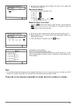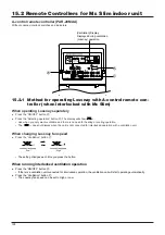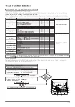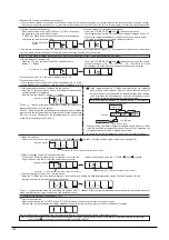
177
14.2 Installing the Lossnay M-NET Remote Controller
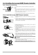
14.2.1 Mount the switch box.
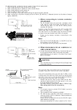
1. Install the switch box (purchased separately) as explained below.
Note:
●
Be sure to install the switch box with the clearance shown in the illustration at
the left. (Check the space between the unit and any projections, such as a
stud.)
●
Leave a space of 120 mm or more below the Lossnay M-NET remote con-
troller so that a screwdriver can be used.
2. Purchase the thin copper wiring conduit, lock nuts and bushings separately.
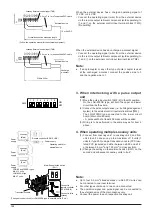
1. Pull out approximately 80 mm of cable from the wall and remove the insulation
at the end.
2. Use putty to seal the cable hole in order to prevent insects from damaging the
wiring and to prevent condensation on the Lossnay M-NET remote controller
circuit board. If this hole is not sealed well, the Lossnay M-NET remote con-
troller circuit board may be damaged.
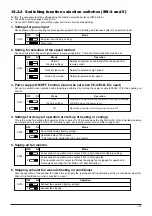
3. Connect the cable to the terminal board at the bottom rear of the Lossnay M-
NET remote controller unit.
●
The cable does not have polarity.
●
When connecting stranded cable, hold down the tab on the terminal board
while inserting the cable.
●
The cable connects to the main terminal board when it is inserted into the bot-
tom terminal.
●
When disconnecting the cable, hold down the tab while pulling out the cable.
●
After inserting the cable, slightly tug on it to check that it does not easily dis-
connect. If the cable is not securely connected, a short-circuit or malfunction
may occur.
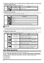
4. Remove the Lossnay M-NET remote controller cover using a standard screw-
driver. Attach the Lossnay M-NET remote controller unit to the switch box
using the two enclosed cross-recessed pan head screws. Use a standard
screwdriver with a blade that is 4 mm or wider to remove the cover.
CAUTION:
●
Forcing off the cover using a screwdriver that is less than 4 mm wide may
result in damage to the equipment or injuries.
●
Attach the Lossnay M-NET remote controller to a level surface. Do not over-
tighten the screws. Tight screws could damage or deform the case.
Switch box
Outline of Lossnay
remote controller
Projecting
object such as
a stud
40 mm or more
11
10
80
Leading
wire
Insula-
tion
Sheath
Wall
Cable
Seal with putty
One switch box
(with cover)
Wiring plpe
Unit (mm)
Button:
Press here.
Insert the cable.
Lossnay M-NET remote
controller cover
14.2.2 Install the Lossnay M-NET Remote Controller.
Summary of Contents for Lossnay PZ-41SLB-E
Page 4: ...CHAPTER 1 Ventilation for Healthy Living Lossnay Unit ...
Page 17: ......
Page 18: ...CHAPTER 2 Lossnay Construction and Principle ...
Page 24: ...CHAPTER 3 General Technical Considerations ...
Page 41: ......
Page 42: ...CHAPTER 4 Characteristics ...
Page 56: ...53 CHAPTER 4 Characteristics ...
Page 57: ...54 CHAPTER 4 Characteristics ...
Page 59: ......
Page 60: ...CHAPTER 5 System Design Recommendations ...
Page 68: ...CHAPTER 6 Examples of Lossnay Applications ...
Page 83: ......
Page 84: ...CHAPTER 7 Installation Considerations ...
Page 88: ...CHAPTER 8 Filtering for Freshness ...
Page 96: ...CHAPTER 9 Service Life and Maintenance ...
Page 98: ...CHAPTER 10 Ventilation Standards in Each Country ...
Page 101: ......
Page 102: ...CHAPTER 11 Lossnay Q and A ...
Page 108: ...Lossnay Remote Controller ...
Page 109: ......
Page 197: ...MEMO ...
Page 198: ...Y04 002 Jul 2004 MEE ...

