1
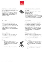
Installation of the knee lifter
1 . Pull out knee lifter shafts (on the right and
left) as far as possible, and set them.
2 . Install the driving crank on each shaft.
3 . Set a link between the right and left driving
cranks to connect them.
4 . Install the knee lifter lever on the left driving
crank.
5 . The operating force can be lightened by
connecting a link with the inside screw Ⓐ in
the left driving crank as shown in the dotted
line of the figure. However, in this case the
operation amount of the knee lifter lever is
increased.
PREPARATION FOR OPERATION
1
Adjustment of the needle stopping position
1 . Adjustment of “UP” position
When the pedal is kicked down by heel, the machine stops at “UP” position.
If marks deviate larger than 3 mm, adjust as follows.
( 1 ) Disconnect the plug (12pins) of cable from the machine head.
( 2 ) Run the machine and stop at “UP” position.
( 3 ) While holding the pulley, insert the “Adjusting tool” in the hole Ⓐ, then turn the tool.
2 . Adjustment of “Down” position
When the pedal is “Neutral” the machine stops at “Down” position.
If marks deviate large than 3 mm, adjust as follows.
( 1 ) Disconnect the plug (12pins) of cable from the machine head.
( 2 ) Run the machine and stop at “Down” position.
( 3 ) While holding the pulley, insert the “Adjusting tool” in the hole Ⓑ, then turn the tool.
3 .
Confirm the stop operation, then set the plug (12pins) coming from the machine head into the
receptacle.
USAGE PRECAUTION
Timing mark
Rotating direction
1st mark
Up position
Down position
White
Black
3rd mark
3rd mark
1st mark
Adjusting tool
later
earlier
Black mark
White mark
Timing of the needle
Ⓐ
Ⓑ
Knee lifter shaft
Driving crank
Knee lifter lever
Collar
Hinged screw
Link
screw Ⓐ
— 1 —


