115
Outdoor unit
PC board
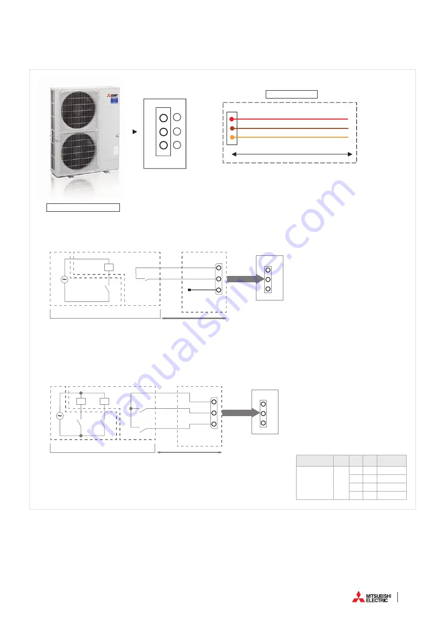
‹Circuit for activation of low noise operation›
Connection mode
PAC-SC36NA
Red
Brown
Orange
Max 10 m
2
3
1
SILENT MODE
- MR.SLIM - POWER LIMITATION
MITSUBISHI ELECTRIC
/ FUNCTION AND SETTINGS
1
3
A
C
Orange
Brown
Red
D
B
E
X
X
SW1
F
CNDM
A Circuit diagram example (low noise mode)
B On-site arrangement
C External input adapter (PAC-SC36NA-E)
X: Relay
D Outdoor unit control board
E Max. 10 m
F Power supply for relay
1
3
F
A
C
D
X
Y
SW2
SW3
X
Y
Orange
Brown
Red
CNDM
B
E
A Circuit diagram example (Demand function)
B On-site arrangement
X, Y: Relay
C External input adapter (PAC-SC36NA-E)
D Outdoor unit control board
E Max. 10 m
F Power supply for relay
Low noise mode (on-site modification)
By performing the following modification, operation noise
of the outdoor unit can be reduced by about 3-4 dB.
The low noise mode will be activated when a commer
-
cially available timer or the contact input of an ON/OFF
switch is added to the CNDM connector (option) on the
control board of the outdoor unit.
• The ability varies according to the outdoor temperature
and conditions, etc.
1 Complete the circuit as shown when using the external
input adapter (PAC-SC36NA-E). (Option)
2 SW7-1 (Outdoor unit control board): OFF
3 SW1 ON: Low noise mode
SW1 OFF: Normal operation
Demand function (on-site modification)
By performing the following modification, energy
consumption can be reduced to 0–100% of the normal
consumption.
The demand function will be activated when a commer
-
cially available timer or the contact input of an ON/OFF
switch is added to the CNDM connector (option) on the
control board of the outdoor unit.
1 Complete the circuit as shown when using the external
input adapter
(PAC-SC36NA-E). (Option)
2 By setting SW7-1 on the control board of the outdoor
unit, the energy consumption (compared to the normal
consumption) can be limited as shown below.
SW7-1 SW2 SW3
Energy
consumption
Demand function
ON
OFF OFF
100%
ON
OFF
75%
ON
ON
50%
OFF
ON
0% (Stop)
Summary of Contents for M-SERIES
Page 1: ...Practical installation guide DX ...
Page 2: ......
Page 3: ......
Page 5: ...3 ...
Page 37: ...35 ...
Page 39: ...37 MITSUBISHI ELECTRIC COMMERCIAL ...
Page 49: ...47 ...
Page 61: ...59 MITSUBISHI ELECTRIC REPLACE TECHNOLOGY ...
Page 75: ...73 MITSUBISHI ELECTRIC REPLACE TECHNOLOGY COMMERCIALE ...
Page 76: ...74 Ventilation ...
Page 77: ...75 MITSUBISHI ELECTRIC VENTILATION ...
Page 111: ...109 ...
Page 118: ......
Page 119: ......


