3 Installation
MITSUBISHI CNC
94
3.3.5 Optional Unit (Memory Expansion Unit / Function Expansion Unit)
(Note)
For details on how to install the optional unit, refer to the installation procedure sheet attached to the optional
unit.
This chapter explains how to install optional unit alone as an example.
If installing memory expansion unit as a second optional unit, refer to the installation procedure sheet.
If installing multiple optional units, refer to the installation procedure sheet.
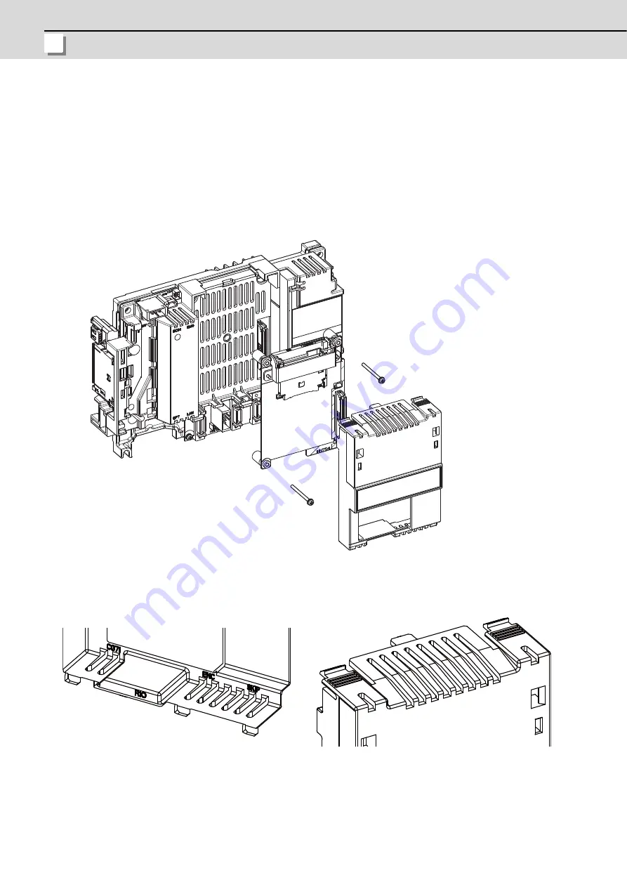
(1) Remove the ADONCCB connector’s cover of the control unit.
(2) Connect the optional unit to the control unit’s ADONCCB connector.
(3) Fix the optional unit with two screws (on the upper right and the bottom left) and mount the back cover.
[Back cover Installation]
(1) Insert the three tabs on the bottom edge of the cover into the
control unit.
(2) Insert two snap-fits on the top right and left edges of the cover
into the control unit.
Summary of Contents for M70V Series
Page 1: ......
Page 13: ......
Page 15: ......
Page 17: ......
Page 19: ......
Page 21: ......
Page 25: ......
Page 26: ...1 1 System Configuration ...
Page 36: ...11 2 General Specifications ...
Page 110: ...85 3 Installation ...
Page 120: ...95 4 Connection ...
Page 173: ...4 Connection MITSUBISHI CNC 148 ...
Page 174: ...149 付録 Ap 1 章 149 Appendix 1 Cable ...
Page 220: ...195 付録 Ap 2 章 195 Appendix 2 EMC Installation Guidelines ...
Page 232: ...207 付録 Ap 3 章 207 Appendix 3 Restrictions for Lithium Batteries ...
Page 241: ...Appendix 3 Restrictions for Lithium Batteries MITSUBISHI CNC 216 ...
Page 242: ...217 付録 Ap 4 章 217 Appendix 4 Precautions for Compliance to UL c UL Standards ...
Page 246: ......
Page 250: ......


