M70V Series Connection Manual
4.6 Connection of Scan I/O card
147
4.6 Connection of Scan I/O card
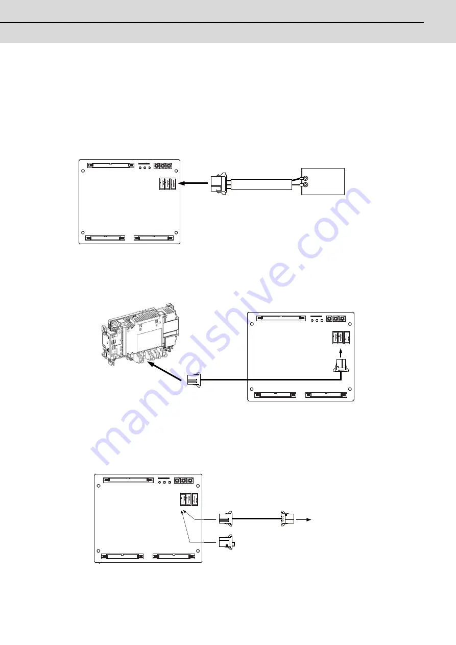
(1) External power supply (DCIN)
24VDC is required for the HR347/HR357 card operation. Prepare a stabilized power supply that satisfies the
following specifications.
Output: 24VDC±5%
Ripple: ±5
%
(P-P)
Rated output current: 2.5A
* The rated output current is the value when using 60mA × 32 points for the machine output.
Prepare a power supply that satisfies the 24VDC output's total output current and control current (0.5A).
(2) Connecting the remote I/O communication cable (RIO3A/B)
(a) Connection of the RIO3A connector
Connect the RIO3A to the RIO1 connector of the control unit or the RIO3 of the operation panel I/O unit.
(b) Connection of the RIO3B connector
Multiple remote I/O units can be used, as long as the total No. of occupied stations connected with serial links
is less than eight. (Refer to "Connection: Connection of Remote I/O Unit" for details.) HR357 occupies three
stations, so the remote I/O units can be connected to the RIO3B in combinations of 5 stations or less. Connect
a terminator to the RIO3B when it is not connected to any device.
DCIN
HR357
F070
0V(RG)
Y
A
B
25
1
CF35
(Scan DI/DO : 64/64)
ISP
8
1
DIO
SCAN2 SCAN1
RIO3
DCIN
B
A
CF31
CF33
20
1
20
1
(DO : 32)
(DO : 32)
ALM3
24IN
ALM2
5OUT
ALM1
cable
24VDC
RIO1
RIO3
HR357
A
A
B
25
1
CF35
(Scan DI/DO : 64/64)
ISP
8
1
DIO
SCAN2 SCAN1
RIO3
DCIN
B
A
CF31
CF33
20
1
20
1
(DO : 32)
(DO : 32)
ALM3
24IN
ALM2
5OUT
ALM1
FCUA-R211
1
2
3
X
Control unit
R IO3
HR 357
B
R - TM
FC UA-DX1xx
A
B
25
1
CF35
(Scan DI/DO : 64/64)
ISP
8
1
DIO
SCAN2
SCAN1
RIO3
DCIN
B
A
CF31
CF33
20
1
20
1
(DO : 32)
(DO : 32)
ALM3
24IN
ALM2
5OUT
ALM1
FCUA-R211
1
2
3
X
Terminator
To the next remote I/O unit
Summary of Contents for M70V Series
Page 1: ......
Page 13: ......
Page 15: ......
Page 17: ......
Page 19: ......
Page 21: ......
Page 25: ......
Page 26: ...1 1 System Configuration ...
Page 36: ...11 2 General Specifications ...
Page 110: ...85 3 Installation ...
Page 120: ...95 4 Connection ...
Page 173: ...4 Connection MITSUBISHI CNC 148 ...
Page 174: ...149 付録 Ap 1 章 149 Appendix 1 Cable ...
Page 220: ...195 付録 Ap 2 章 195 Appendix 2 EMC Installation Guidelines ...
Page 232: ...207 付録 Ap 3 章 207 Appendix 3 Restrictions for Lithium Batteries ...
Page 241: ...Appendix 3 Restrictions for Lithium Batteries MITSUBISHI CNC 216 ...
Page 242: ...217 付録 Ap 4 章 217 Appendix 4 Precautions for Compliance to UL c UL Standards ...
Page 246: ......
Page 250: ......


