M70V Series Connection Manual
2.2 Control Unit
21
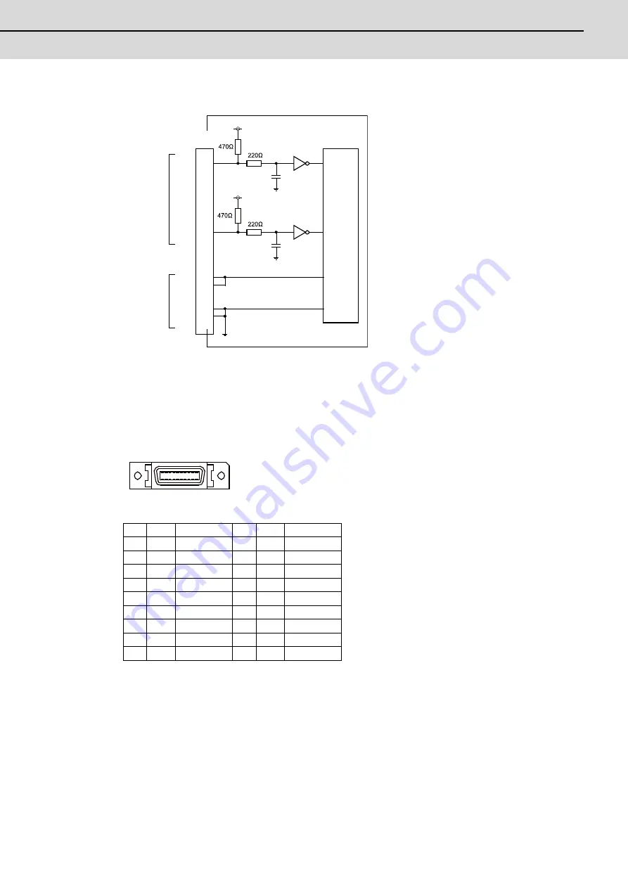
(c) 5V manual pulse generator input/output circuit
When using the synchronous feed encoder and the manual pulse generator at the same time, connect
the manual pulse generator to the operation panel I/O unit or use a distribution cable made by the
machine tool builder.
(14) Skip input 8ch (SKIP)
* Connect connector case with FG pattern.
<Cable side connector type>
Plug: 10120-3000VE
Shell: 10320-52F0-008
Recommended manufacturer: 3M
1
COM
11
COM
2
I
SKIP0
12
I
SKIP1
3
I
SKIP2
13
I
SKIP3
4
NC
14
NC
5
COM
15
COM
6
NC
16
NC
7
I
SKIP4
17
I
SKIP5
8
I
SKIP6
18
I
SKIP7
9
NC
19
NC
10
NC
20
NC
0V
+5V
8
7
18
17
10
20
1
11
0V
+5V
+5V
+5V
0V
0V
0V
HA1A
HA2A
HA1B
HA2B
Connector
pin No.
Control
circuit
Signal
input
Power
output
10
1
20
11
Summary of Contents for M70V Series
Page 1: ......
Page 13: ......
Page 15: ......
Page 17: ......
Page 19: ......
Page 21: ......
Page 25: ......
Page 26: ...1 1 System Configuration ...
Page 36: ...11 2 General Specifications ...
Page 110: ...85 3 Installation ...
Page 120: ...95 4 Connection ...
Page 173: ...4 Connection MITSUBISHI CNC 148 ...
Page 174: ...149 付録 Ap 1 章 149 Appendix 1 Cable ...
Page 220: ...195 付録 Ap 2 章 195 Appendix 2 EMC Installation Guidelines ...
Page 232: ...207 付録 Ap 3 章 207 Appendix 3 Restrictions for Lithium Batteries ...
Page 241: ...Appendix 3 Restrictions for Lithium Batteries MITSUBISHI CNC 216 ...
Page 242: ...217 付録 Ap 4 章 217 Appendix 4 Precautions for Compliance to UL c UL Standards ...
Page 246: ......
Page 250: ......


