
10
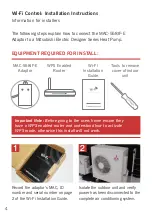
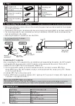
4. Connecting the Wi-Fi Adaptor
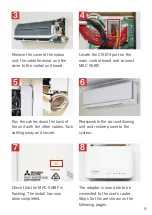
• Before dismantling the indoor unit turn off and verify the power has been disconnected to the complete
air-conditioning system.
• Dismantle the indoor unit in accordance with the service manual and locate CN105 on the Main control PCB.
• The connecting cable (5-core) connected to a room air conditioner (CN105) should be mounted at the
room air conditioner or its vicinity.
• Cable length outside air conditioner: less than 50cm.
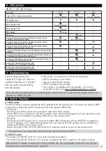
Mounting
cord clamp
Cable
mount
Connecting
cable (5-core)
Mounting
cord clamp
Screw
Screw
Taken out from
the left side
Taken out from
the right side
Screw
Screw
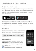
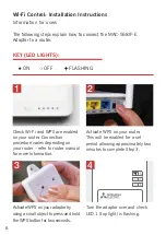
Establishing Wi-Fi connection
After connecting the Wi-Fi adaptor to the air conditioner and reassembling the system, the Wi-Fi adaptor
must register with the access point or Wi-Fi router (to communicate with the server). For this Wi-Fi
adaptor, the use of WPS-Push is recommended. (Refer to 8.)
1) Hold down the WPS switch on the Wi-Fi adaptor for about 2 seconds to activate WPS-Push.
When WPS-Push on the Wi-Fi adaptor is ready to communicate with the access point, LED 1 flashes
at a 0.5-second interval.
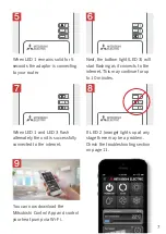
2) Activate WPS-Push on the access point.
3) When WPS-Push is successfully enabled, LED 1 lights up for 5 seconds. If it failed, LED 2 lights up for
5 seconds, so try again from step 1.
Main causes that WPS failed are as follows:
Communication distance (from the Wi-Fi adaptor to access point), access point settings (encryption,
authentication, limit of connections, etc.) Refer to the instruction manual for more information.
Do not install the Wi-Fi adaptor
inside the indoor unit.
CASE1
CASE2
(For details on each system, see the relevant instruction manual.)
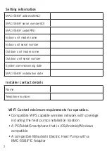
5. Specifications
Input Voltage
DC12.7V (from indoor unit)
Power consumption
MAX 2W
Size W×H×D (mm)
88×49×18.5
Weight
105g (including cable )
RF channel
1ch ~ 13ch
Radio protocol
IEEE 802.11b/g/n (20)
Encryption
AES
Authentication
PSK
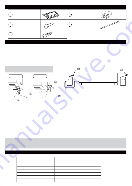
3. Parts
1
Adaptor unit
[with connecting cable
(5-core)]
1
4
Mounting cord
clamp
1
2
Screw for mounting
3.5×16
1
5
Fastener
(for bundling the
wires)
1
3
Screw for mounting
4×16
1
Summary of Contents for MAC-558IF-E
Page 1: ...1 INSTALLATION GUIDE ...


