7
en
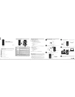
Run the connecting cable in the space on the back of the unit as shown in the above figure.
Tuck cabling away and secure it.
Note: Make sure that the connecting cable will not get caught on or between the installation plate and
the wall, or between the indoor unit and the installation plate.
Failure to do so may cause damage to the connecting cable resulting in communication prob
-
lems.
Make sure that the connecting cable will not come out from the indoor unit.
• Slip the clip over the edge of corner box to fix the interface unit .
Note: Mount the interface unit on the side of the indoor unit.
• To check the LED indication after setup, remove the interface unit from the holder .
Example of mounting on the left side of indoor unit
Note: Interface unit can also be mounted on the right side of the indoor unit.
Side of the Indoor unit
• Insert the clip into the holder until it clicks.
• Insert the interface unit into the holder until it clicks.
When mounting on the outer side of indoor unit (Wall mounted indoor unit)
Indoor unit
Corner box
Interface
unit
Corner box
Clip
Clip
Holder
Interface unit
Holder
Connecting cable
RH79A066H03_01en.indd 7
RH79A066H03_01en.indd 7
2021/11/16 15:57:45
2021/11/16 15:57:45


