11. Troubleshooting
11
−
2
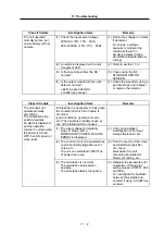
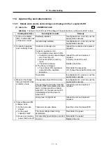
Class II trouble
Investigation items
Remedy
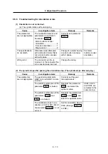
(1) Check the input power voltage
10%
−
15% 50Hz
200~10%
−
15% 60Hz
(1) Return the voltage to normal
if abnormal.
Or, ensure a voltage
capacity to maintain the
voltage at the left in
excessive states (during
acceleration/deceleration or
cutting).
(2) An alarm is displayed on the unit
7-segment LED.
(2) Refer to section 11.4.1.
(3) Is the input signal from the NC
normal?
(3) Check using the NC
SPINDLE MONITOR
SCREEN.
The unit operated
normally before, but
now suddenly will not
operate.
(4) Is the output waveform from each
detector normal?
•
Built-in speed detector
•
1024P/rev encoder
(4) Check the waveform using a
synchroscope and readjust
or replace the detector.
Class III trouble
Investigation items
Remedy
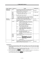
In this state it is necessary to fully grasp
the condition in which the trouble is
occurring.
(Load conditions, operation modes,
etc.) The trouble is probably cause by
one of the following three causes:
(1) The input voltage momentarily
stops or drops, and a
MOMENTARY POWER FAILURE
ERROR is displayed.
(1) Carry out a detailed
investigation of the input
voltage fluctuation, etc.
(2) The control circuit mis-operated due
to an abnormally large amount of
noise, etc.
The unit can withstand 1600V/1us
of power line noise.
(2) Find the source of the noise,
and install a surge killer,
etc., there.
Reconsider the unit
grounding and detector
shield, grounding, etc.
The unit does not
operate normally
sometimes.
The orientation stop
position deviates.
An alarm is displayed,
but the operation
returns to normal when
the power is turned
OFF then ON again, or
when reset.
(3) The orientation is incorrect.
The orientation stop position
deviates.
The orientation takes a long time.
(3) Readjust the parameters for
orientation. (Change the
setting values of SP001, 002
and 006.)
Or, investigate for backlash
between the spindle and
encoder if using a 1024P/rev
encoder.

