11. Troubleshooting
11
−
18
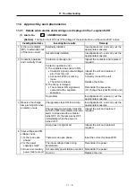
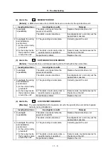
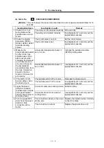
Investigation items
Investigation results
Remedy
The trouble is eliminated by
increasing the setting value.
Reconsider and change the setting
value.
8 Check the spindle
synchronization time
constant of the spindle
parameter.
The trouble is not eliminated by
increasing the setting value.
Return the setting to the original
value. Investigate item 9, and carry
out the appropriate measures.
The trouble is eliminated by
increasing the setting value.
Change the setting value.
9 Check the spindle
parameter (SP010:
PGS) setting value.
The trouble is not eliminated by
increasing the setting value.
Return the setting to the original
value. Investigate item 10, and carry
out the appropriate measures.
The correct values are not set.
Set the correct values.
10 Check the spindle
parameter (SP177 to
SP190, SP257 and
following) setting
values.
No particular problem.
Replace the unit, or readjust/replace
the position detector.
The trouble is eliminated by
changing the bit5 setting value.
Change the bit5 setting value.
11 If the alarm occurs
during synchronous
tap, check the spindle
parameter (SP193:
SPECT) bit5 setting
value.
The trouble is not eliminated by
changing the bit5 setting value.
Return bit5 to the original setting
value. Investigate item 12, and carry
out the appropriate measures.
The trouble is eliminated by
increasing the setting value.
Reconsider and change the setting
value.
12 Check the spindle
parameter
synchronous tap time
constant.
The trouble is not eliminated by
increasing the setting value.
Return the setting to the original
value. Investigate item 13, and carry
out the appropriate measures.
The trouble is eliminated by
increasing the setting value.
Change the setting value.
13 Check the spindle
parameter (SP009:
PGT) setting value.
The trouble is not eliminated by
increasing the setting value.
Return the setting to the original
value. Investigate item 14, and carry
out the appropriate measures.
The correct values are not set.
Set the correct values.
14 Check the spindle
parameter (SP193 to
SP222, SP257 and
following) setting
values.
No particular problem.
Replace the unit, or readjust/replace
the position detector.
The tracking error amount (droop amount) can be calculated using the following equation.
This alarm will occur if this value exceeds the setting value of each excessive error width.
Droop amount (No. of pulses) =
{Spindle speed (rpm)/60}
×
No. of pulses per rotation (
∗
1)
Position loop gain (sec
-1
)
(
∗
1) The No. of pulses per rotation is 4096.


