Appendix
A
−
7
Appendix 3 Theoretical acceleration and deceleration times
In the calculation described below, load torque is assumed to be zero. Therefore, acceleration and
deceleration times determined here somewhat differ from actual acceleration and deceleration times.
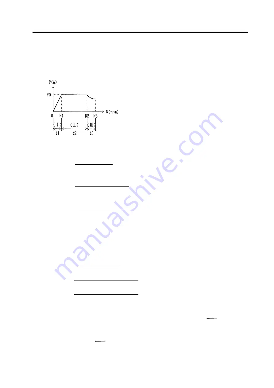
(1) Definition
(2) Acceleration/deceleration time "t"
1) Constant torque zone
t1 =
1.03
×
GD
2
×
N1
2
375
×
Po
(sec)
2) Constant output (power) zone
t2 =
1.03
×
GD
2
×
(N2
2
−
N1
2
)
2
×
375
×
Po
(sec)
3) Reduced output zone
t3 =
1.03
×
GD
2
×
(N3
2
−
N2
2
)
2
×
375
×
Po
×
N2
(sec)
Therefore, accel/decel. Time t (0
→
N
3
) is,
t = t
1
+ t
2
+ t
3
(sec)
Example
: GD
2
L
= 0.11kgfm
2
For motor SJ-PF3.7-01
From specification 2, GD
2
M
= 0.034kgm
2
thus, GD
2
= 0.034 + 0.11 = 0.144kgfm
2
t
1
=
1.03
×
0.144
×
1500
2
375
×
3700
×
1.2
= 0.200 (sec)
t
2
=
1.03
×
0.144
×
(6000
2
−
1500
2
)
2
×
375
×
3700
×
1.2
= 1.503 (sec)
t
3
=
1.03
×
0.144
×
(8000
2
−
6000
2
)
3
×
375
×
3700
×
1.2
×
6000
= 1.465 (sec)
Unit conversion
:
Forth : 1kgf = 9.8N
Speed
: 1rpm =
2
π
60
rad/s
Torque : 1kgfm = 9.8Nm = 10
2
kgm
Output (power) : 1kW = 1/1.3596HP
P =
ω
To = (2
π
N
60
)
×
9.8T
(Notes)
1) "Po" is (Rated power
×
1.2).
Example
: For spindle of 2.2/3.7kW,
Po = 3700
×
1.2 = 4440 (W)
2)
GD
2
= (Motor GD
2
) +
(GD
2
converted into load to motor shaft) (kg
•
m
2
)
P :
Output
[w]
ω
: Angular velocity [rad/s]
To : Torque [N
−
m]
N :
Speed
[rpm]
T :
Torque
[kgm]


