3. Functions
3
−
2
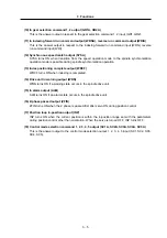
(5) Orientation start command input (ORC)
1) This is the orientation start signal. Orientation will start regardless of the run command (SRN,
SRI) when ORC is ON.
2) If either a forward run (SRN) or reverse run (SRI) command is input when ORC is OFF, the
motor will start rotating at the commanded speed again.
3) When an orientation command is input, the orientation will have the priority.
(6) Gear selection command 1, 2 input (GR1, GR2)
1) The spindle gear step for carrying out orientation or various position control operations is
selected.
2) Four types of gears shown below can be selected according to the combination of the GR1
and GR2 2-bit input.
3) Do not change the signal when an orientation command or servo ON command is input.
GR 2
GR 1
Parameter used to set the gear ratio
0
0
SP025 (GRA1), SP029 (GRB1)
0
1
SP026 (GRA2), SP030 (GRB2)
1
0
SP027 (GRA3), SP031 (GRB3)
1
1
SP028 (GRA4), SP032 (GRB4)
(7) Indexing forward run command input (WRN), reverse run command input (WRI)
1) This is the command input for forward run indexing or reverse run indexing during multi-point
orientation. This signal is valid only when the orientation start signal is ON.
2) Forward run indexing takes place in the CCW direction looking from the motor shaft, and
reverse run indexing takes place in the CW direction.
(8) Control mode selection command 1, 2, 3, 4, 5 input (SC1, SC2, SC3, SC4, SC5)
The operation mode for position control of the spindle drive unit is selected with bit
correspondence. The selections are as follow.
SC5 SC4 SC3 SC2 SC1
Operation
mode
0
0
1
1
0 ~ 0
0
1
0
1
Synchronous tapping operation mode
0
0
1
1
1 ~ 1
0
1
0
1
Mode not used
1
1
0
0
0 ~ 0
0
1
0
1
Spindle synchronization operation mode
(Note)
Bit selections other than the above will validate the normal speed operation mode.


