Chapter 5 Connections
Contents
5. Connections ...................................................................................................................
5 - 1
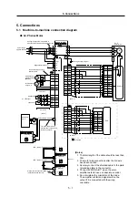
5.1 Machine-to-machine connection diagram .............................................................
5 - 1
5.2 Spindle amplifier connections ................................................................................
5 - 3
5.2.1 Main circuit terminal block and control circuit terminal block ..........................
5 - 3
5.2.2 Signal names and applications of the main circuit terminal block and
control circuit terminal block ............................................................................
5 - 5
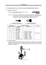
5.2.3 Usage method of the control circuit terminal block (MDS-B-SPJ2-02 to 075)
5 - 6
5.3 Spindle motor and detector connection .................................................................
5 - 7
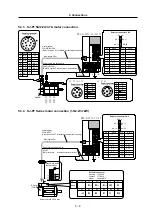
5.3.1 SJ-P0.2A/0.4A motor connection ....................................................................
5 - 7
5.3.2 SJ-P0.75A motor connection...........................................................................
5 - 7
5.3.3 SJ-P1.5A/2.2A/3.7A motor connection............................................................
5 - 8
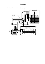
5.3.4 SJ-PF Series motor connection (1.5/2.2/3.7kW).............................................
5 - 8
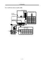
5.3.5 SJ-PF Series motor connection (5.5/7.5kW)...................................................
5 - 9
5.3.6 SJ-PF Series motor connection (11kW).......................................................... 5 - 10
5.4 Power supply connection ........................................................................................ 5 - 11
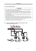
5.4.1 Connection example when controlling the electromagnetic switch
with an external sequence circuit .................................................................... 5 - 11
5.4.2 Connection example when controlling the electromagnetic switch
with the MDS-B-SPJ2...................................................................................... 5 - 12
5.4.3 Connection example when controlling the electromagnetic switch
with the MDS-B-CV/CR ................................................................................... 5 - 13
5.4.4 Output circuit of the electromagnetic switch control signal (MCON
∗
)............. 5 - 13
5.5 Regenerative resistor connection............................................................................ 5 - 14
5.6 Relation to the main circuit .................................................................................... 5 - 15
5.6.1 Selection of the main circuit wire, no-fuse breaker and electromagnetic
contactor .......................................................................................................... 5
-
15
5.6.2 Input/output DIO relay...................................................................................... 5 - 15
5.7 Control circuit cables and connectors ..................................................................... 5 - 16


