5. Connections
5
−
11
5.4 Power supply connection
CAUTION
1. Do not exceed the power supply voltage, capacity, etc., specified in the controller specifications.
Failure to observe this could result in damage or failure.
2. Always install a no-fuse breaker or earth leakage breaker for safety, and be sure the power is
turned OFF at the breakers during abnormalities or inspections. A large rush current is flowed
when the power is turned ON. Refer to section 5.6, and select an appropriate no-fuse breaker or
earth leakage breaker.
3. The wire size will differ according to the amplifier capacity. Refer to the table in section 5.6, and
select the appropriate wire size.
4. Always install an electromagnetic switch for safety, and be sure that the power turns OFF when
abnormalities occur. There is an electromagnetic switch control function in the MDS-B-SPJ2. An
external relay is required for this function. When there is a convertor unit MDS-B-CV in the system,
the electromagnetic switch control function of the convertor can be used.
The MDS-B-CV can directly drive the electromagnetic switch.
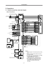
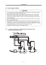
5.4.1 Connection example when controlling the electromagnetic switch
with an external sequence circuit
L1
L2
L3
L11
L21
T1
T2
PE
24VDC
P24
24G
MCON*
1 4
1 1
1 0
CN3
CN1A
CN1B
External
emergency stop
MC1
NFB
M D S - B - S V J 2
Servo amplifier
L1
L2
L3
L11
L21
T1
T2
PE
3-phase
200 to 230V
24VDC
VDD
COM
MC
1 0
5
1 5
CN3
CN1A
CN1B
Mitsubishi
CNC
24VDC
←
Alarm
Cable SH21
Emergency
stop
→
←
Alarm
M D S - B - S P J 2
Spindle amplifier
MC1
External emergency stop
RA
Create a sequence that turns
OFF when alarms occur.
Emergency stop
→
Class 3
grounding
or higher
Terminator
MDS-A-MT
Class 3
grounding
or higher


