5. Connections
5
−
13
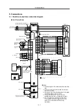
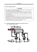
5.4.3 Connection example when controlling the electromagnetic switch
with the MDS-B-CV/CR
The following is a connection example when there is a convertor unit MDS-B-CV/CR is the system.
The electromagnetic switch control signal (MC1) of the MDS-B-CV/CR can directly drive the
electromagnetic switch.
Convertor unit
M DS - B- CV
/CR
NFB
3-phase
200~230V
MC1
M D S - B - S P J 2
Spindle amplifier
L1
L2
L3
L11
L21
T1
T2
PE
24VDC
P24
24G
MCON*
1 4
1 1
1 0
CN3
Spindle amplifier, etc.
L1
L2
L3
MC1
L11
L21
L+
L-
CN4
CN4
AC reactor
B-AL
MDS -B- Vx
/
MDS - B- S P
L11
L21
L+
L-
CN1A
CN1B
CN1A
CN1B
MC1
24VDC
Emergency stop
→
←
Alarm
Cable SH21
Emergency stop
→
←
Alarm
Emergency stop
→
←
Alarm
(Note)
External
emergency stop Mitsubishi
CNC
Class 3
grounding
or higher
•
Refer to the "MDS-B Series Specification Manual BNP-B3759" for details about the convertor unit
MDS-B-CV/CR.
CAUTION
Always install a convertor unit AC reactor MDS-B-AL. Always wire the MSD-B-SPJ2 main circuit (L1,
L2, L3), control power (L11, L21) and spindle amplifier, etc., control power (L11, L21) to the primary
side of the MDS-B-AL.
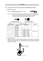
5.4.4 Output circuit of the electromagnetic switch control signal (MCON
∗
)
A relay or photocoupler can be driven.
Install a diode for inductive loads.
When using an internal power supply
When using an external power supply
Inductive load
P24
24G
24VDC
MCON*
output
Spindle amplifier
The spindle amplifier will
fail if the diode is installed
with reverse polarity.
Load
Allowable current : 40mA or less
Rush current : 100m or less
P24
24G
24VDC
MCON*
output
Spindle amplifier
The spindle amplifier will
fail if the diode is installed
with reverse polarity.
27VDC or less
Load
Allowable current : 40mA or less
Rush current : 100m or less


