MDS-E/EH Series Instruction Manual
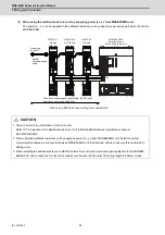
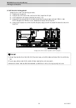
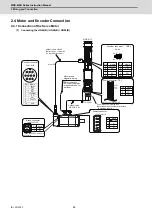
2 Wiring and Connection
70
IB-1501229-F
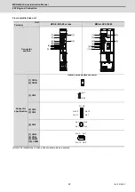
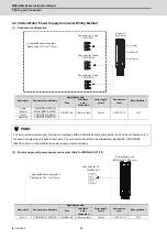
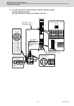
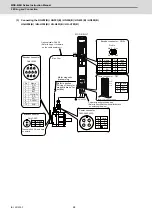
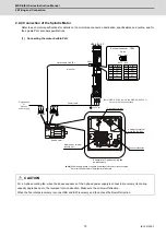
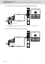
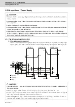
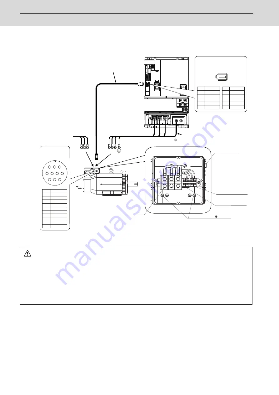
(5) Connecting the HG-H1502
CAUTION
1. For a 3-phase cooling fan, when the phase sequence of the 3-phase power supply is connected reversely, its cooling
capacity degrades due to the reversed rotation direction. Make sure the air blowoff direction.
When the fan rotates reversely, reconnect BU and BW reversely, and then check the blowoff direction.
2. The user must connect the motor thermal(OHS1 OHS2 maximum switching voltage 30V DC) with PLC and construct a
sequence in which an alarm occurs in an OPEN state.
3. Dynamic brake unit is required for HG-H1502. Refer to section "Dynamic brake unit wiring" for details.
LG
RQ*
SD*
2
4
6
8
10
P5 (+5V)
RQ
SD
BT
1
3
5
7
9
CN2L
CMV1-R10P
8
4
5
7
6
9
10
1
2
3
1 RQ
2 RQ*
3
4 BAT
5 LG(GND)
6 SD
7 SD*
8 P5(+5V)
9
10 SHD
U V W
BU BW
BV
8
9
2+6
%8
:
%:
%9
2+6
MDS-EH-V1-200
LU
LV
LW
CNT
(U,V,W) M8
screw
(OHS1,OHS2) M4 screw
(BU,BV,BW) M4 screw
Max. 30m
Pin
Name
Optional cable: CNV2E
(Refer to Appx. 1 for details
on the cable treatment.)
Power wire and grounding wire
(Refer to Specification manual for det ails
on selecting the wire.)
Encoder connector
Motor power
terminal
block
Thermal sensor
terminal
block
Encoder connector
Grounding terminal ( ) M6 screw
Cooling fan terminal block
3-phase 400V
power supply
Encoder connector
:
CN2L
Name
Pin
Name
Pin
Pin No.
Exhaust air
Cooling air inlet
No.10 No.2
No.9 No.1
Summary of Contents for MDS-E
Page 1: ......
Page 3: ......
Page 15: ......
Page 17: ......
Page 19: ......
Page 21: ......
Page 31: ......
Page 32: ...1 IB 1501229 F 1 Installation ...
Page 76: ...45 IB 1501229 F 2 Wiring and Connection ...
Page 132: ...101 IB 1501229 F 3 Safety Function ...
Page 142: ...111 IB 1501229 F 4 Setup ...
Page 277: ...MDS E EH Series Instruction Manual 4 Setup 246 IB 1501229 F ...
Page 278: ...247 IB 1501229 F 5 Servo Adjustment ...
Page 351: ...MDS E EH Series Instruction Manual 5 Servo Adjustment 320 IB 1501229 F ...
Page 352: ...321 IB 1501229 F 6 Spindle Adjustment ...
Page 404: ...373 IB 1501229 F 7 Troubleshooting ...
Page 455: ...MDS E EH Series Instruction Manual 7 Troubleshooting 424 IB 1501229 F ...
Page 456: ...425 IB 1501229 F 8 Maintenance ...
Page 475: ...MDS E EH Series Instruction Manual 8 Maintenance 444 IB 1501229 F ...
Page 476: ...445 IB 1501229 F 9 Power Backup System ...
Page 494: ...463 IB 1501229 F 10 Appx 1 Cable and Connector Assembly ...
Page 504: ...473 IB 1501229 F 11 Appx 2 D A Output Specifications for Drive Unit ...
Page 514: ...483 IB 1501229 F 12 Appx 3 Protection Function ...
Page 523: ...MDS E EH Series Instruction Manual 12 Appx 3 Protection Function 492 IB 1501229 F ...
Page 524: ...493 IB 1501229 F 13 Appx 4 Compliance to EC Directives ...
Page 528: ...497 IB 1501229 F 14 Appx 5 EMC Installation Guidelines ...
Page 540: ...509 IB 1501229 F 15 Appx 6 Higher Harmonic Suppression Measure Guidelines ...
Page 550: ......
Page 554: ......


