MDS-E/EH Series Instruction Manual
2 Wiring and Connection
83
IB-1501229-F
2.6 Wiring of the Motor Brake
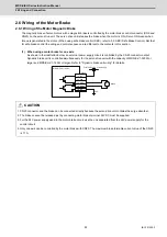
2.6.1 Wiring of the Motor Magnetic Brake
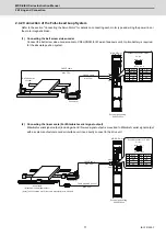
The magnetic brake of servo motors with a magnetic brake is controlled by the motor brake control connector (CN9 and
CN20) on the servo drive unit. The servo drive unit releases the brake when the motor is ON. (Servo ON means when
torque is generated in the motor.) When using safe brake control (SBC), refer to 3.3. SBC (Safe Brake Control). Not that
for safe brake control the wiring and control sequence are different to the contents in this section.
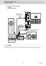
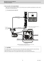
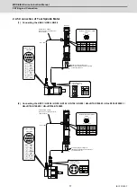
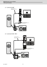
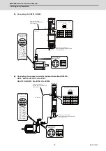
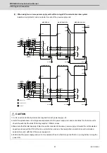
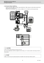
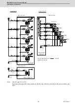
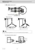
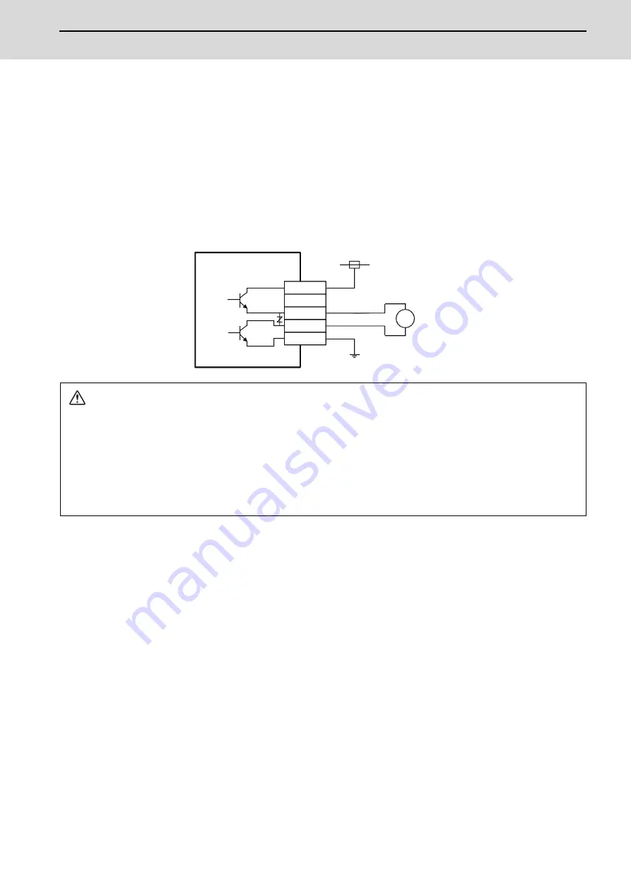
(1) When using a motor brake for one axis
As shown in the illustration below, an external power supply circuit is controlled by the CN20 connector output.
Dynamic brake unit is controlled simultaneously for the servo drive unit with the capacity of MDS-E-V1-320W or
larger and MDS-EH-V1-160W or larger. Refer to "Dynamic brake unit wiring" for details.
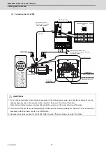
CAUTION
1. CN20 connector and the brake can be connected directly because the servo drive unit contains the surge absorber.
2. The brakes cannot be released just by connecting motor brake terminal. 24VDC must be supplied.
3. For the 24V power supply used in the motor brake circuit, use the one separated from the 24V power supply for the
control circuit.
4. Only one axis can be controlled by the motor brake with CN20. The maximum brake tolerable current value of the CN20
is 1.7A.
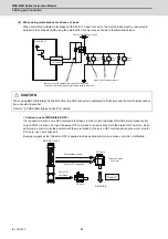
CN20
1A : P24
2A : DBR
3A : MBR1
3B : MBR2
1B : 24G
24G
MDS-E/EH-V1/V2/V3
Brake
External 24VDC power supply
Summary of Contents for MDS-E
Page 1: ......
Page 3: ......
Page 15: ......
Page 17: ......
Page 19: ......
Page 21: ......
Page 31: ......
Page 32: ...1 IB 1501229 F 1 Installation ...
Page 76: ...45 IB 1501229 F 2 Wiring and Connection ...
Page 132: ...101 IB 1501229 F 3 Safety Function ...
Page 142: ...111 IB 1501229 F 4 Setup ...
Page 277: ...MDS E EH Series Instruction Manual 4 Setup 246 IB 1501229 F ...
Page 278: ...247 IB 1501229 F 5 Servo Adjustment ...
Page 351: ...MDS E EH Series Instruction Manual 5 Servo Adjustment 320 IB 1501229 F ...
Page 352: ...321 IB 1501229 F 6 Spindle Adjustment ...
Page 404: ...373 IB 1501229 F 7 Troubleshooting ...
Page 455: ...MDS E EH Series Instruction Manual 7 Troubleshooting 424 IB 1501229 F ...
Page 456: ...425 IB 1501229 F 8 Maintenance ...
Page 475: ...MDS E EH Series Instruction Manual 8 Maintenance 444 IB 1501229 F ...
Page 476: ...445 IB 1501229 F 9 Power Backup System ...
Page 494: ...463 IB 1501229 F 10 Appx 1 Cable and Connector Assembly ...
Page 504: ...473 IB 1501229 F 11 Appx 2 D A Output Specifications for Drive Unit ...
Page 514: ...483 IB 1501229 F 12 Appx 3 Protection Function ...
Page 523: ...MDS E EH Series Instruction Manual 12 Appx 3 Protection Function 492 IB 1501229 F ...
Page 524: ...493 IB 1501229 F 13 Appx 4 Compliance to EC Directives ...
Page 528: ...497 IB 1501229 F 14 Appx 5 EMC Installation Guidelines ...
Page 540: ...509 IB 1501229 F 15 Appx 6 Higher Harmonic Suppression Measure Guidelines ...
Page 550: ......
Page 554: ......


