MDS-E/EH Series Instruction Manual
2 Wiring and Connection
84
IB-1501229-F
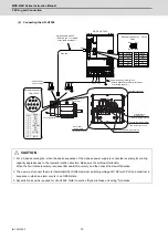
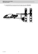
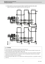
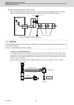
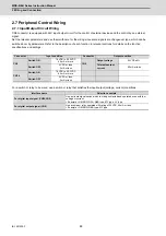
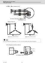
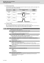
(2) When using motor brakes for 2 axes or 3 axes
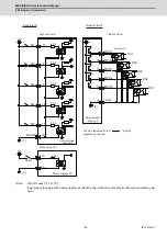
When controlling multiple motor brakes with 2-axis or 3-axis drive units, the motor brakes must be connected in
parallel to the connector CN9 using the external 24V driving relay as shown in the illustration below.
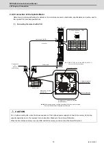
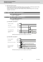
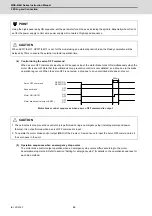
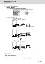
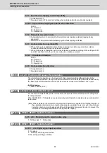
< Caution in use of MDS-E/EH-V2/V3 >
It is required to input a servo OFF command to all axes in order to turn the brake ON with a motor brake control
output (CN20) of drive unit. Input the servo OFF command to an axis cannot turn the brake ON. Therefore, when
performing a control to fix the position with the motor brake by the servo OFF command during the motor stop for
PLC axis, use 1-axis drive unit.
During emergency stop, the servo OFF is applied to all axes at same time, so a brake control is not affected.
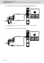
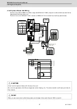
CAUTION
When using SBC (Safe Brake Control) function, the CN9 connector is dedicated to the M axis and the motor brakes cannot
be connected in parallel.
Refer to "3.3 SBC (Safe Brake Control)" for details.
CN9
8 : SBC1
10: DOCOM
MDS-E/EH-V3
S-axis
brake
External 24VDC power supply
Always install surge absorbers.
M-axis
brake
L-axis
brake
Be careful not to mistake the polarity of the diode.
The drive unit is damaged when the polarity is reversed.
MDS-E/EH-V2/V3
Servo ON
command
NC axis
Axis drop
The brake does
not work.
Danger !
Servo OFF command
Motor brake control
PLC axis
Summary of Contents for MDS-E
Page 1: ......
Page 3: ......
Page 15: ......
Page 17: ......
Page 19: ......
Page 21: ......
Page 31: ......
Page 32: ...1 IB 1501229 F 1 Installation ...
Page 76: ...45 IB 1501229 F 2 Wiring and Connection ...
Page 132: ...101 IB 1501229 F 3 Safety Function ...
Page 142: ...111 IB 1501229 F 4 Setup ...
Page 277: ...MDS E EH Series Instruction Manual 4 Setup 246 IB 1501229 F ...
Page 278: ...247 IB 1501229 F 5 Servo Adjustment ...
Page 351: ...MDS E EH Series Instruction Manual 5 Servo Adjustment 320 IB 1501229 F ...
Page 352: ...321 IB 1501229 F 6 Spindle Adjustment ...
Page 404: ...373 IB 1501229 F 7 Troubleshooting ...
Page 455: ...MDS E EH Series Instruction Manual 7 Troubleshooting 424 IB 1501229 F ...
Page 456: ...425 IB 1501229 F 8 Maintenance ...
Page 475: ...MDS E EH Series Instruction Manual 8 Maintenance 444 IB 1501229 F ...
Page 476: ...445 IB 1501229 F 9 Power Backup System ...
Page 494: ...463 IB 1501229 F 10 Appx 1 Cable and Connector Assembly ...
Page 504: ...473 IB 1501229 F 11 Appx 2 D A Output Specifications for Drive Unit ...
Page 514: ...483 IB 1501229 F 12 Appx 3 Protection Function ...
Page 523: ...MDS E EH Series Instruction Manual 12 Appx 3 Protection Function 492 IB 1501229 F ...
Page 524: ...493 IB 1501229 F 13 Appx 4 Compliance to EC Directives ...
Page 528: ...497 IB 1501229 F 14 Appx 5 EMC Installation Guidelines ...
Page 540: ...509 IB 1501229 F 15 Appx 6 Higher Harmonic Suppression Measure Guidelines ...
Page 550: ......
Page 554: ......

