


MDS-E/EH Series Instruction Manual
2 Wiring and Connection
94
IB-1501229-F
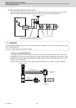
(2) Protective functions
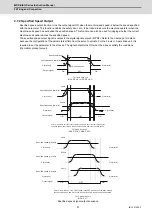
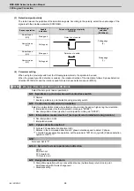
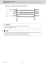
[1] Gate shutoff after a winding changeover
When the L-coil selection command (LCS) is used to perform low-speed winding -> high-speed winding
switching, or vice-versa, the gate is shut off during contactor operation time in order to protect the spindle drive
unit's main circuit. The gate shutoff time is determined by the "Coil changeover gate cutoff timer" (SP114)
setting. The standard time setting should be used, as a shorter time can cause contactor burn damage.
(Refer to "Spindle control output 5" Coil changing (bit 6) for details.)
【
#13114
】
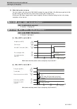
SP114 MKT Coil changeover gate cutoff timer
Set the time required to cut off the gate when turning OFF/ON the coil switch contactor.
The value should be longer than the coil switch contactor's OFF/ON time.
The standard setting is "150".
---Setting range---
0 to 3500 (ms)
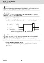
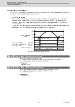
[2] Current limit after coil changeover
Following a coil changeover, the current is limited (SP116) for the period specified by the current limit timer
(SP115) in order to stabilize control. Because position loop control (synchronous tap, C-axis control, etc.) that
occurs immediately after a coil changeover will result in unstable control, be sure that position commands
specified by the sequence is input after the current limit is cancelled.
【
#13115
】
SP115 MKT2 Coil changeover current limit timer
Set the time required to limit the current immediately after the coil switch contactor ON/OFF is
completed and the gate is turned ON.
The standard setting is "250".
---Setting range---
0 to 3500 (ms)
【
#13116
】
SP116 MKIL Coil changeover current limit value
Set the time required to limit the current immediately after the coil switch contactor ON/OFF is
completed and the gate is turned ON.
The standard setting is "120".
---Setting range---
0 to 999 (Short-time rated %)
Summary of Contents for MDS-E
Page 1: ......
Page 3: ......
Page 15: ......
Page 17: ......
Page 19: ......
Page 21: ......
Page 31: ......
Page 32: ...1 IB 1501229 F 1 Installation ...
Page 76: ...45 IB 1501229 F 2 Wiring and Connection ...
Page 132: ...101 IB 1501229 F 3 Safety Function ...
Page 142: ...111 IB 1501229 F 4 Setup ...
Page 277: ...MDS E EH Series Instruction Manual 4 Setup 246 IB 1501229 F ...
Page 278: ...247 IB 1501229 F 5 Servo Adjustment ...
Page 351: ...MDS E EH Series Instruction Manual 5 Servo Adjustment 320 IB 1501229 F ...
Page 352: ...321 IB 1501229 F 6 Spindle Adjustment ...
Page 404: ...373 IB 1501229 F 7 Troubleshooting ...
Page 455: ...MDS E EH Series Instruction Manual 7 Troubleshooting 424 IB 1501229 F ...
Page 456: ...425 IB 1501229 F 8 Maintenance ...
Page 475: ...MDS E EH Series Instruction Manual 8 Maintenance 444 IB 1501229 F ...
Page 476: ...445 IB 1501229 F 9 Power Backup System ...
Page 494: ...463 IB 1501229 F 10 Appx 1 Cable and Connector Assembly ...
Page 504: ...473 IB 1501229 F 11 Appx 2 D A Output Specifications for Drive Unit ...
Page 514: ...483 IB 1501229 F 12 Appx 3 Protection Function ...
Page 523: ...MDS E EH Series Instruction Manual 12 Appx 3 Protection Function 492 IB 1501229 F ...
Page 524: ...493 IB 1501229 F 13 Appx 4 Compliance to EC Directives ...
Page 528: ...497 IB 1501229 F 14 Appx 5 EMC Installation Guidelines ...
Page 540: ...509 IB 1501229 F 15 Appx 6 Higher Harmonic Suppression Measure Guidelines ...
Page 550: ......
Page 554: ......


