MDS-E/EH Series Instruction Manual
3 Safety Function
105
IB-1501229-F
(2) Dedicated wiring STO function
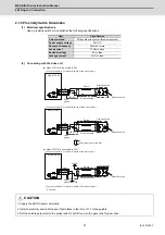
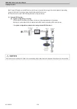
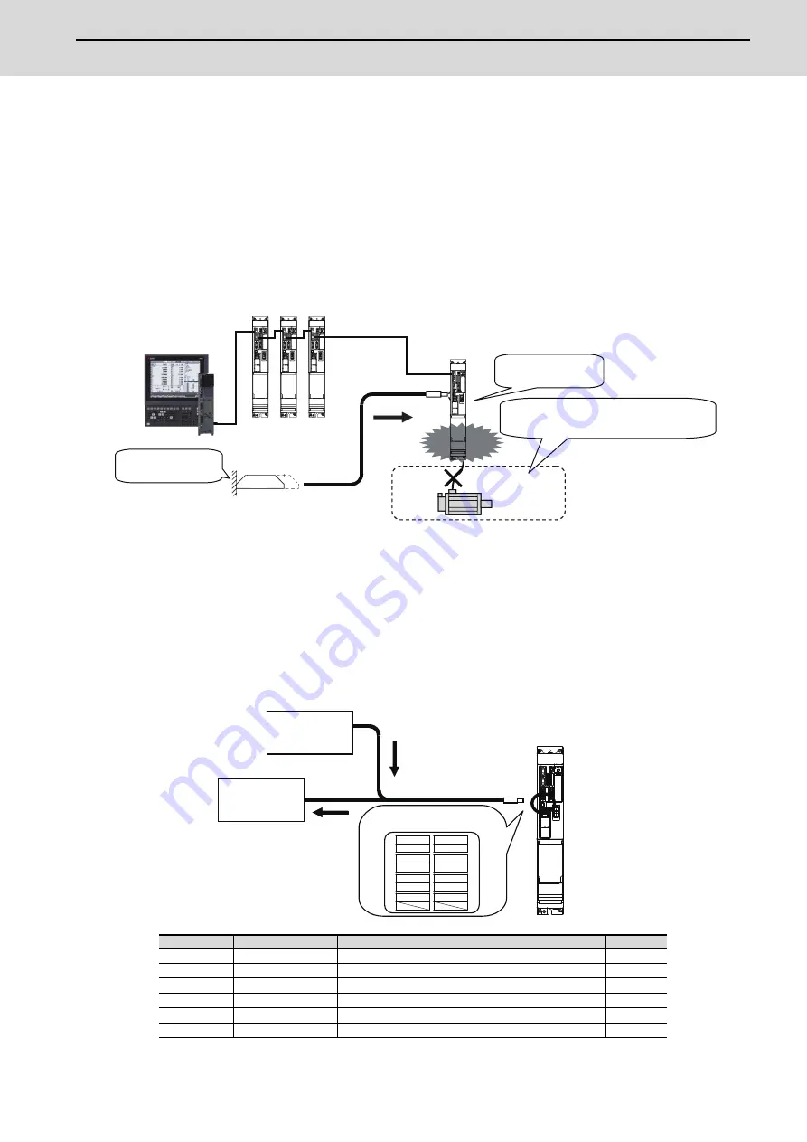
[1] System configuration
This method is used to shut off the motor power with STO function only for the specific axis.
For example, to shut off the motor power with STO function only for the magazine rack axis, install a safety
door for tool change and directly connect the door open/close signal to the STO signal input (CN8) of the drive
unit. Warning A4(sub-number 0001) is detected while STO function is shutting off the motor power.
(Note)
Always insert the provided short-circuit connector to CN8 for other than magazine rack axis and
cause short circuit in the STO signal.
Manufacturer : Tyco Electronics < Type > Connector set: MR-D05UDL3M-B
< A system configuration example when using dedicated wiring STO function >
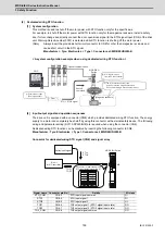
[2] Input/output signal and operation sequences
The drive unit is equipped with a connector (CN8) which provides dedicated wiring STO function. The energy
supply to a motor can completely be shutoff by using this connector with external safety device. The following
wiring and parameter setting (SV113,SP229/bit8) are required when using the connector (CN8).
Dedicated wiring STO function can be disabled by inserting the following connector to CN8.
Manufacturer : Tyco Electronics < Type > Connector set: MR-D05UDL3M-B
Connector for dedicated wiring STO signal (CN8) and signal array
Signal name Connector pin No.
Details
I/O class
STO_COM
CN8-3
STO input signal common
DI
STO1
CN8-4
STO input signal 1
DI
STO2
CN8-5
STO input signal 2
DI
TOF1
CN8-6
TOF output signal 1 (STO1 signal input state)
DO
TOF2
CN8-7
TOF output signal 2 (STO2 signal input state)
DO
TOF_COM
CN8-8
TOF output signal common
DO
CNC
CN8
MDS-E/EH
(1) External door open
(Dual signal input)
(2) STO signal is input
from the CN8 connector
(3) The STO function shuts off the
power for only the magazine rack axis.
Drive unit: Warning A4 (sub-number 0001)
Optical communication
Shutoff
command
STO1, STO2 signal
[Magazine rack axis]
STO shutoff
via CN8
Door
Series
CN8
STO1
STO2
TOF1
TOF2
7
8
STO1
5
STO_COM
6
TOF1
3
STO2
4
TOF_COM
1
TOF2
2
Safety input signal
IO unit
for NC controller
MDS-E/EH Series
Connector for dedicated wiring
STO input/output signal (CN8)
Summary of Contents for MDS-E
Page 1: ......
Page 3: ......
Page 15: ......
Page 17: ......
Page 19: ......
Page 21: ......
Page 31: ......
Page 32: ...1 IB 1501229 F 1 Installation ...
Page 76: ...45 IB 1501229 F 2 Wiring and Connection ...
Page 132: ...101 IB 1501229 F 3 Safety Function ...
Page 142: ...111 IB 1501229 F 4 Setup ...
Page 277: ...MDS E EH Series Instruction Manual 4 Setup 246 IB 1501229 F ...
Page 278: ...247 IB 1501229 F 5 Servo Adjustment ...
Page 351: ...MDS E EH Series Instruction Manual 5 Servo Adjustment 320 IB 1501229 F ...
Page 352: ...321 IB 1501229 F 6 Spindle Adjustment ...
Page 404: ...373 IB 1501229 F 7 Troubleshooting ...
Page 455: ...MDS E EH Series Instruction Manual 7 Troubleshooting 424 IB 1501229 F ...
Page 456: ...425 IB 1501229 F 8 Maintenance ...
Page 475: ...MDS E EH Series Instruction Manual 8 Maintenance 444 IB 1501229 F ...
Page 476: ...445 IB 1501229 F 9 Power Backup System ...
Page 494: ...463 IB 1501229 F 10 Appx 1 Cable and Connector Assembly ...
Page 504: ...473 IB 1501229 F 11 Appx 2 D A Output Specifications for Drive Unit ...
Page 514: ...483 IB 1501229 F 12 Appx 3 Protection Function ...
Page 523: ...MDS E EH Series Instruction Manual 12 Appx 3 Protection Function 492 IB 1501229 F ...
Page 524: ...493 IB 1501229 F 13 Appx 4 Compliance to EC Directives ...
Page 528: ...497 IB 1501229 F 14 Appx 5 EMC Installation Guidelines ...
Page 540: ...509 IB 1501229 F 15 Appx 6 Higher Harmonic Suppression Measure Guidelines ...
Page 550: ......
Page 554: ......

