

MDS-E/EH Series Instruction Manual
4 Setup
114
IB-1501229-F
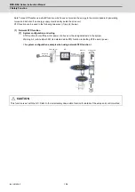
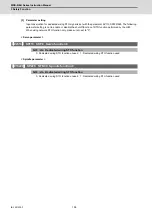
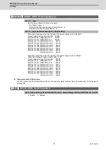
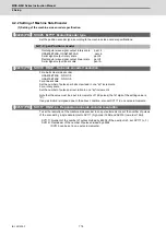
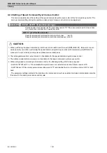
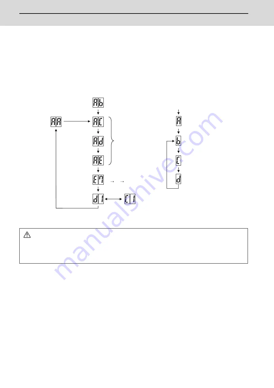
4.1.3 Transition of LED Display After Power Is Turned ON
When the NC power is turned ON and the initial communication with the NC is started, each unit will automatically
execute self-diagnosis and initial settings for operation, etc. The LEDs on the front of the units will change as shown
below according to the progression of these processes.
If an alarm occurs, the alarm No. will appear on the LEDs. Refer to section "LED display when alarm or warning occurs"
for details on the alarm displays.
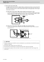
CAUTION
1. Always input emergency stop when starting the servo system.
2. Do not insert or extract the external STO input connector (CN8) after starting the servo system. Motor power will be shut
off and it may cause the collision of machine.
Executing
initial
communication with NC
Drive unit initialization complete
Waiting for NC power start up
Emergency stop state
The LED will alternate between
F#
E7
not lit.
(# is the set axis No.)
Repeats lighting and going out.
(1st axis in the display example)
NC power ON
Waiting for NC
power start up
NC power OFF
NC power ON
LED display
Servo ON state
Drive units
Emergency stop state
NC power
ON
LED display
In servo ON
(Charge completed)
Power supply unit
In initializing
Initializing completed
Contactor OFF
Ready OFF state
In ready ON
(In Charging)
Contactor ON
Servo OFF state
Summary of Contents for MDS-E
Page 1: ......
Page 3: ......
Page 15: ......
Page 17: ......
Page 19: ......
Page 21: ......
Page 31: ......
Page 32: ...1 IB 1501229 F 1 Installation ...
Page 76: ...45 IB 1501229 F 2 Wiring and Connection ...
Page 132: ...101 IB 1501229 F 3 Safety Function ...
Page 142: ...111 IB 1501229 F 4 Setup ...
Page 277: ...MDS E EH Series Instruction Manual 4 Setup 246 IB 1501229 F ...
Page 278: ...247 IB 1501229 F 5 Servo Adjustment ...
Page 351: ...MDS E EH Series Instruction Manual 5 Servo Adjustment 320 IB 1501229 F ...
Page 352: ...321 IB 1501229 F 6 Spindle Adjustment ...
Page 404: ...373 IB 1501229 F 7 Troubleshooting ...
Page 455: ...MDS E EH Series Instruction Manual 7 Troubleshooting 424 IB 1501229 F ...
Page 456: ...425 IB 1501229 F 8 Maintenance ...
Page 475: ...MDS E EH Series Instruction Manual 8 Maintenance 444 IB 1501229 F ...
Page 476: ...445 IB 1501229 F 9 Power Backup System ...
Page 494: ...463 IB 1501229 F 10 Appx 1 Cable and Connector Assembly ...
Page 504: ...473 IB 1501229 F 11 Appx 2 D A Output Specifications for Drive Unit ...
Page 514: ...483 IB 1501229 F 12 Appx 3 Protection Function ...
Page 523: ...MDS E EH Series Instruction Manual 12 Appx 3 Protection Function 492 IB 1501229 F ...
Page 524: ...493 IB 1501229 F 13 Appx 4 Compliance to EC Directives ...
Page 528: ...497 IB 1501229 F 14 Appx 5 EMC Installation Guidelines ...
Page 540: ...509 IB 1501229 F 15 Appx 6 Higher Harmonic Suppression Measure Guidelines ...
Page 550: ......
Page 554: ......


