MDS-E/EH Series Instruction Manual
4 Setup
122
IB-1501229-F
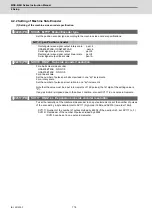
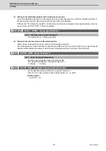
4.2.3 Setting of Distance-coded Reference Scale
(1) Setting of the base specifications
In order to set the distance-coded reference scale, the following setting follows "Setting of Machine Side Encoder".
【
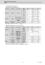
#2281(PR)
】
SV081 SPEC2 Servo specification 2
bit 7 : szchk Distance-coded reference scale reference mark
Set the number of reference marks to be passed during the reference position calculation. If an error
occurs in passing the reference mark, the neighboring mark is checked. When an error is detected
three times in total, the alarm "42" will occur.
0: Check at 4 points (standard) 1: Check at 3 points
bit 3 : absc Distance-coded reference scale
0: Disable 1: Enable
【
#2330(PR)
】
SV130 RPITS Base reference mark interval
Set the interval between the base reference marks arranged at regular intervals on the distance-
coded reference scale. When the base reference mark interval (SV130) and the reference mark's
auxiliary interval are in the specified relationship, the distance-coded reference scale is judged to be
connected.
Following is the specified relationship.
(SV130×1000) / SV131 >= 4 (No remainder)
---Setting range---
0 to 32767 (mm)
【
#2331(PR)
】
SV131 DPITS Auxiliary reference mark interval
Set the auxiliary interval of reference mark in the distance-coded reference scale.
---Setting range---
0 to 32767 (
μ
m)
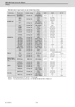
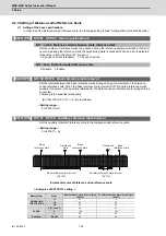
Incremental scale of distance-coded reference scale
< Examples of SV130/131 setting >
Manufacturer
Series
Base reference mark interval [mm]
(SV130)
Auxiliary reference mark interval [
μ
m]
(SV131)
HEIDENHAIN
CORPORATION
LF
20
4
LS
20
20
LB
80
40
FAGOR
S, M, C and G
20
20
F
100
100
L
80
40
Renishaw
RSLM
80
20
Base reference mark interval
(SV130)
Auxiliary reference mark interval
(SV131)
Reference
mark
Base
reference mark
Base
reference mark
Reference
mark
Base
reference mark
Summary of Contents for MDS-E
Page 1: ......
Page 3: ......
Page 15: ......
Page 17: ......
Page 19: ......
Page 21: ......
Page 31: ......
Page 32: ...1 IB 1501229 F 1 Installation ...
Page 76: ...45 IB 1501229 F 2 Wiring and Connection ...
Page 132: ...101 IB 1501229 F 3 Safety Function ...
Page 142: ...111 IB 1501229 F 4 Setup ...
Page 277: ...MDS E EH Series Instruction Manual 4 Setup 246 IB 1501229 F ...
Page 278: ...247 IB 1501229 F 5 Servo Adjustment ...
Page 351: ...MDS E EH Series Instruction Manual 5 Servo Adjustment 320 IB 1501229 F ...
Page 352: ...321 IB 1501229 F 6 Spindle Adjustment ...
Page 404: ...373 IB 1501229 F 7 Troubleshooting ...
Page 455: ...MDS E EH Series Instruction Manual 7 Troubleshooting 424 IB 1501229 F ...
Page 456: ...425 IB 1501229 F 8 Maintenance ...
Page 475: ...MDS E EH Series Instruction Manual 8 Maintenance 444 IB 1501229 F ...
Page 476: ...445 IB 1501229 F 9 Power Backup System ...
Page 494: ...463 IB 1501229 F 10 Appx 1 Cable and Connector Assembly ...
Page 504: ...473 IB 1501229 F 11 Appx 2 D A Output Specifications for Drive Unit ...
Page 514: ...483 IB 1501229 F 12 Appx 3 Protection Function ...
Page 523: ...MDS E EH Series Instruction Manual 12 Appx 3 Protection Function 492 IB 1501229 F ...
Page 524: ...493 IB 1501229 F 13 Appx 4 Compliance to EC Directives ...
Page 528: ...497 IB 1501229 F 14 Appx 5 EMC Installation Guidelines ...
Page 540: ...509 IB 1501229 F 15 Appx 6 Higher Harmonic Suppression Measure Guidelines ...
Page 550: ......
Page 554: ......

