

MDS-E/EH Series Instruction Manual
4 Setup
157
IB-1501229-F
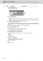
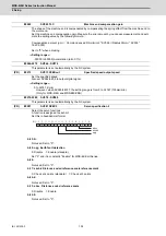
Set this parameter to adjust the pull up distance when the vertical axis pull up function is enabled. When the
pull up function is enabled and this parameter is set to "0", for a rotary motor, 8/1000 of a rotation at the motor
end is internally set as the pull up distance, and for a linear motor, 80[
μ
m] is set.
Related parameters:
SV032 : The pull up direction is determined. When "0" is set, the alarm occurs.
SV033/bitE : Start-up of the pull up function
SV048 : Set the drop prevention time. When "0" is set, the alarm occurs.
---Setting range---
0 to 2000 (
μ
m)
Not used. Set to "0".
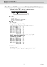
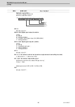
Set the scale model gain (position response) in OMR-FF control.
Set the same value as SV003(PGN1).
Increase the setting value to perform a high-speed machining such as a fine arc or to improve the path er-
ror.Lower the value when vibration occurs during acceleration/deceleration.
Set to "0" when not using OMR-FF control.
---Setting range---
0 to 300 (rad/s)
Not used. Set to "0".
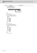
Set the current feed forward rate in OMR-FF control.
The standard setting is "10000".
Setting value of "0" is equal to "10000(100%)" setting.
Set to "0" when not using OMR-FF control.
---Setting range---
0 to 32767 (0.01%)
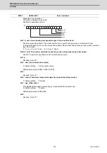
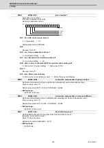
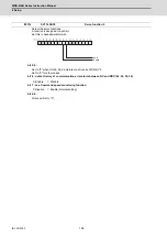
Select the servo functions.
A function is assigned to each bit.
Set this in hexadecimal format.
bit F-9 :
Not used. Set to "0".
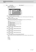
bit 8 : sto Dedicated wiring STO function
Set this parameter to use dedicated wiring STO function.
0: Dedicated wiring STO function unused 1: Dedicated wiring STO function used
(Only for MDS-E/EH and MDS-EJ/EJH)
bit 7 : nmerc Machine error compensation amount
(Note) Do not turn ON the NC power supply with the setting as disable (set to "1"). The initial parameter error
alarm is detected.
0: Enable (Normal setting) 1: Disable
bit 0 : omrffon OMR-FF control enabled
0: Disable 1: Enable
#2295
SV095 ZUPD
Vertical axis pull up distance
#2296-2305
SV096 - SV105
#2306
SV106 PGM
OMR-FF scale model gain
#2307-2311
SV107 - SV111
#2312
SV112 IFF
OMR-FF current feed forward gain
#2313
SV113 SSF8
Servo function 8
omrffon
sto
nmerc
Summary of Contents for MDS-E
Page 1: ......
Page 3: ......
Page 15: ......
Page 17: ......
Page 19: ......
Page 21: ......
Page 31: ......
Page 32: ...1 IB 1501229 F 1 Installation ...
Page 76: ...45 IB 1501229 F 2 Wiring and Connection ...
Page 132: ...101 IB 1501229 F 3 Safety Function ...
Page 142: ...111 IB 1501229 F 4 Setup ...
Page 277: ...MDS E EH Series Instruction Manual 4 Setup 246 IB 1501229 F ...
Page 278: ...247 IB 1501229 F 5 Servo Adjustment ...
Page 351: ...MDS E EH Series Instruction Manual 5 Servo Adjustment 320 IB 1501229 F ...
Page 352: ...321 IB 1501229 F 6 Spindle Adjustment ...
Page 404: ...373 IB 1501229 F 7 Troubleshooting ...
Page 455: ...MDS E EH Series Instruction Manual 7 Troubleshooting 424 IB 1501229 F ...
Page 456: ...425 IB 1501229 F 8 Maintenance ...
Page 475: ...MDS E EH Series Instruction Manual 8 Maintenance 444 IB 1501229 F ...
Page 476: ...445 IB 1501229 F 9 Power Backup System ...
Page 494: ...463 IB 1501229 F 10 Appx 1 Cable and Connector Assembly ...
Page 504: ...473 IB 1501229 F 11 Appx 2 D A Output Specifications for Drive Unit ...
Page 514: ...483 IB 1501229 F 12 Appx 3 Protection Function ...
Page 523: ...MDS E EH Series Instruction Manual 12 Appx 3 Protection Function 492 IB 1501229 F ...
Page 524: ...493 IB 1501229 F 13 Appx 4 Compliance to EC Directives ...
Page 528: ...497 IB 1501229 F 14 Appx 5 EMC Installation Guidelines ...
Page 540: ...509 IB 1501229 F 15 Appx 6 Higher Harmonic Suppression Measure Guidelines ...
Page 550: ......
Page 554: ......


