MDS-E/EH Series Instruction Manual
4 Setup
161
IB-1501229-F
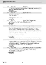
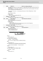
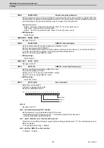
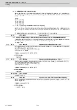
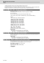
Set the base reference mark intervals of distance-coded reference scale. When the distance-coded refer-
ence scale is not used, set to "0".
The interval of basic reference mark (SV130) and auxiliary interval (SV131) must be in the specified relation-
ship. Other settings cause the initial parameter error (alarm 37).
Following is the specified relationship.
The quotient of (SV130×1000) / SV131 must be 4 or more and leaves no remainder.
Related parameters: SV081/bit7,3, SV131, SV134 to SV137
---Setting range---
0 to 32767 (mm)
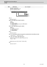
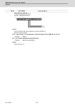
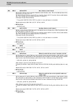
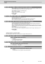
Set the auxiliary interval of reference mark in the distance-coded reference scale. When the distance-coded
reference scale is not used, set to "0".
The interval of basic reference mark (SV130) and auxiliary interval (SV131) must be in the specified relation-
ship. Other settings cause the initial parameter error (alarm 37).
Following is the specified relationship.
The quotient of (SV130×1000) / SV131 must be 4 or more and leaves no remainder.
Related parameters: SV081/bit7,3, SV130, SV134 to SV137
---Setting range---
0 to 32767 (
μ
m)
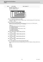
Not used. Set to "0".
Not used. Set to "0".
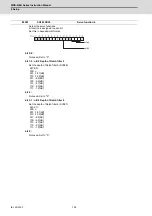
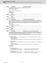
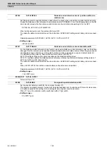
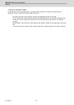
Set this parameter to operate distance-coded reference check when using distance-coded reference scale.
During the distance-coded reference check initial setup (SV137:RAER=-1), set the following items on the NC
drive monitor screen after the distance-coded reference check initial setup warning A3 turns OFF.
SV134=Rn, SV135=Pn, SV136=MPOS
When reference point is set, the warning A3 turns OFF.
To enable the distance-coded reference check function, SV081/bit3=1setting and a battery option are need-
ed.
Related parameters: SV081/bit3,7, SV130, SV131, SV134 to SV137
---Setting range---
-32768 to 32767
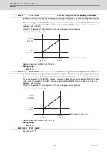
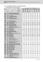
(PR)
#2330
SV130 RPITS
Base reference mark interval
(PR)
#2331
SV131 DPITS
Auxiliary reference mark interval
#2332
SV132
#2333
SV133
#2334
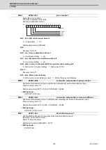
SV134 RRn0
Distance-coded reference check / revolution counter
#2335
SV135 RPn0H
Distance-coded reference check /position within one
rotation High
Summary of Contents for MDS-E
Page 1: ......
Page 3: ......
Page 15: ......
Page 17: ......
Page 19: ......
Page 21: ......
Page 31: ......
Page 32: ...1 IB 1501229 F 1 Installation ...
Page 76: ...45 IB 1501229 F 2 Wiring and Connection ...
Page 132: ...101 IB 1501229 F 3 Safety Function ...
Page 142: ...111 IB 1501229 F 4 Setup ...
Page 277: ...MDS E EH Series Instruction Manual 4 Setup 246 IB 1501229 F ...
Page 278: ...247 IB 1501229 F 5 Servo Adjustment ...
Page 351: ...MDS E EH Series Instruction Manual 5 Servo Adjustment 320 IB 1501229 F ...
Page 352: ...321 IB 1501229 F 6 Spindle Adjustment ...
Page 404: ...373 IB 1501229 F 7 Troubleshooting ...
Page 455: ...MDS E EH Series Instruction Manual 7 Troubleshooting 424 IB 1501229 F ...
Page 456: ...425 IB 1501229 F 8 Maintenance ...
Page 475: ...MDS E EH Series Instruction Manual 8 Maintenance 444 IB 1501229 F ...
Page 476: ...445 IB 1501229 F 9 Power Backup System ...
Page 494: ...463 IB 1501229 F 10 Appx 1 Cable and Connector Assembly ...
Page 504: ...473 IB 1501229 F 11 Appx 2 D A Output Specifications for Drive Unit ...
Page 514: ...483 IB 1501229 F 12 Appx 3 Protection Function ...
Page 523: ...MDS E EH Series Instruction Manual 12 Appx 3 Protection Function 492 IB 1501229 F ...
Page 524: ...493 IB 1501229 F 13 Appx 4 Compliance to EC Directives ...
Page 528: ...497 IB 1501229 F 14 Appx 5 EMC Installation Guidelines ...
Page 540: ...509 IB 1501229 F 15 Appx 6 Higher Harmonic Suppression Measure Guidelines ...
Page 550: ......
Page 554: ......


