


Contents
1 Installation .................................................................................................................................................... 1
1.1 Installation of Servo Motor..................................................................................................................................... 2
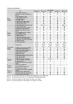
1.1.1 Environmental Conditions ............................................................................................................................ 2
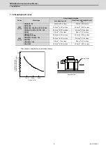
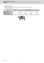
1.1.2 Quakeproof Level ........................................................................................................................................... 3
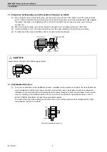
1.1.3 Cautions for Mounting Load (Prevention of Impact on Shaft) ................................................................... 4
1.1.4 Installation Direction...................................................................................................................................... 4
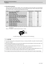
1.1.5 Shaft Characteristics ..................................................................................................................................... 5
1.1.6 Machine Accuracy.......................................................................................................................................... 6
1.1.7 Coupling with the Load.................................................................................................................................. 7
1.1.8 Oil / Water Standards ..................................................................................................................................... 8
1.1.9 Installation of Servo Motor .......................................................................................................................... 11
1.1.10 Cable Stress................................................................................................................................................ 11
1.2 Installation of Spindle Motor................................................................................................................................ 12
1.2.1 Environmental Conditions .......................................................................................................................... 12
1.2.2 Balancing the Spindle Motor (Unit)............................................................................................................. 13
1.2.3 Shaft Characteristics ................................................................................................................................... 15
1.2.4 Machine Accuracy........................................................................................................................................ 15
1.2.5 Coupling with the Fittings ........................................................................................................................... 16
1.2.6 Installation of Rotary Joint and Coolant Joint (Hollow Shaft Specifications) ........................................ 16
1.2.7 Ambient Environment .................................................................................................................................. 22
1.2.8 Installation of Spindle Motor ....................................................................................................................... 22
1.2.9 Connection.................................................................................................................................................... 23
1.2.10 Cable............................................................................................................................................................ 24
1.3 Installation of Tool Spindle Motor ....................................................................................................................... 25
1.3.1 Environmental Conditions .......................................................................................................................... 25
1.3.2 Shaft Characteristics ................................................................................................................................... 25
1.3.3 Installation of Tool Spindle Motor............................................................................................................... 25
1.4 Installation of the Drive Unit ................................................................................................................................ 26
1.4.1 Environmental Conditions .......................................................................................................................... 26
1.4.2 Installation Direction and Clearance .......................................................................................................... 27
1.4.3 Prevention of Entering of Foreign Matter................................................................................................... 29
1.4.4 Panel Installation Hole Work Drawings (Panel Cut Drawings)................................................................. 30
1.4.5 Heating Value................................................................................................................................................ 32
1.4.6 Heat Radiation Countermeasures............................................................................................................... 33
1.5 Installation of the Machine End Encoder............................................................................................................ 36
1.5.1 Spindle Side ABZ Pulse Output Encoder (OSE-1024 Series)................................................................... 36
1.5.2 Spindle Side PLG Serial Output Encoder (TS5690, MU1606 Series) ....................................................... 37
1.6 Noise Measures..................................................................................................................................................... 43
2 Wiring and Connection.............................................................................................................................. 45
2.1 Part System Connection Diagram ....................................................................................................................... 47
2.2 Main Circuit Terminal Block/Control Circuit Connector.................................................................................... 48
2.2.1 Names and Applications of Main Circuit Terminal Block Signals and Control Circuit Connectors..... 48
2.2.2 Connector Pin Assignment ......................................................................................................................... 49
2.2.3 Servo Motor Power Supply Connector Wiring Method............................................................................. 60
2.3 NC and Drive Unit Connection............................................................................................................................. 62
2.3.1 Connection of Optical Communication Cables ......................................................................................... 62
2.3.2 Drive Unit Arrangement ............................................................................................................................... 65
2.4 Motor and Encoder Connection........................................................................................................................... 66
2.4.1 Connection of the Servo Motor ................................................................................................................... 66
2.4.2 Connection of the Full-closed Loop System ............................................................................................. 71
2.4.3 Connection of the Speed Command Synchronization Control System .................................................. 73
2.4.4 Connection of the Spindle Motor ................................................................................................................ 75
2.4.5 Connection of Tool Spindle Motor.............................................................................................................. 77
2.5 Connection of Power Supply ............................................................................................................................... 80
2.5.1 Power Supply Input Connection ................................................................................................................. 80
2.5.2 Connection of the Grounding Cable........................................................................................................... 82
2.6 Wiring of the Motor Brake ................................................................................................................................... 83
2.6.1 Wiring of the Motor Magnetic Brake ........................................................................................................... 83
2.6.2 Dynamic Brake Unit Wiring ......................................................................................................................... 87
2.7 Peripheral Control Wiring..................................................................................................................................... 88
2.7.1 Input/Output Circuit Wiring ......................................................................................................................... 88
2.7.2 Specified Speed Output............................................................................................................................... 91
Summary of Contents for MDS-E
Page 1: ......
Page 3: ......
Page 15: ......
Page 17: ......
Page 19: ......
Page 21: ......
Page 31: ......
Page 32: ...1 IB 1501229 F 1 Installation ...
Page 76: ...45 IB 1501229 F 2 Wiring and Connection ...
Page 132: ...101 IB 1501229 F 3 Safety Function ...
Page 142: ...111 IB 1501229 F 4 Setup ...
Page 277: ...MDS E EH Series Instruction Manual 4 Setup 246 IB 1501229 F ...
Page 278: ...247 IB 1501229 F 5 Servo Adjustment ...
Page 351: ...MDS E EH Series Instruction Manual 5 Servo Adjustment 320 IB 1501229 F ...
Page 352: ...321 IB 1501229 F 6 Spindle Adjustment ...
Page 404: ...373 IB 1501229 F 7 Troubleshooting ...
Page 455: ...MDS E EH Series Instruction Manual 7 Troubleshooting 424 IB 1501229 F ...
Page 456: ...425 IB 1501229 F 8 Maintenance ...
Page 475: ...MDS E EH Series Instruction Manual 8 Maintenance 444 IB 1501229 F ...
Page 476: ...445 IB 1501229 F 9 Power Backup System ...
Page 494: ...463 IB 1501229 F 10 Appx 1 Cable and Connector Assembly ...
Page 504: ...473 IB 1501229 F 11 Appx 2 D A Output Specifications for Drive Unit ...
Page 514: ...483 IB 1501229 F 12 Appx 3 Protection Function ...
Page 523: ...MDS E EH Series Instruction Manual 12 Appx 3 Protection Function 492 IB 1501229 F ...
Page 524: ...493 IB 1501229 F 13 Appx 4 Compliance to EC Directives ...
Page 528: ...497 IB 1501229 F 14 Appx 5 EMC Installation Guidelines ...
Page 540: ...509 IB 1501229 F 15 Appx 6 Higher Harmonic Suppression Measure Guidelines ...
Page 550: ......
Page 554: ......


