MDS-E/EH Series Instruction Manual
4 Setup
215
IB-1501229-F
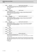
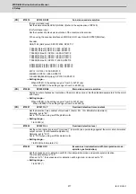
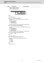
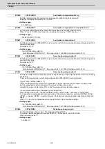
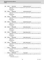
Normally, SP014(PY1) is used.
By setting "SP035/bit2, SP035/bitA or SP036/bit2=1", the excitation rate 2 can be used according to the ap-
plication.
The excitation rate 2 can also be used by setting "the minimum excitation rate 2 changeover request (control
input 5/ bitB) = 1". Refer to SP014(PY1) for adjustment procedures.
Set to "0" when using an IPM spindle motor.
---Setting range---
0 to 100 (%)
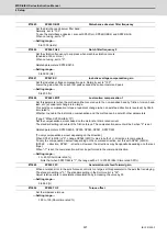
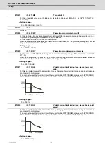
Set the single-rotation position alignment deceleration rate for orientation stopping, phase alignment while
rotating and switching from non-interpolation mode to spindle synchronization mode while rotating.
When the load inertia is larger, the setting value should be smaller.
When the setting value is larger, the orientation in-position and single-rotation position alignment complete
faster, but the impact applied on the machine will increase.
To change the deceleration rate only during rotation command (command F
∆
T
≠
0), set this parameter to-
gether with SP070 (KDDT).
---Setting range---
1 to 32767 (0.1(r/min)/ms)
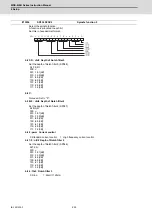
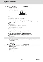
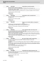
Select the spindle specification.
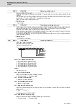
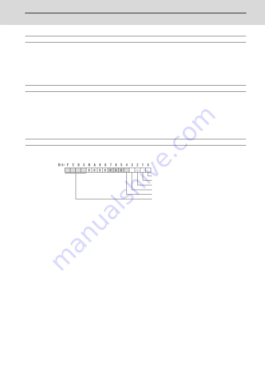
A function is allocated to each bit.
Set this in hexadecimal format.
bit F-C : msr Motor series selection
0: 200V specification IM spindle motor
1: 200V specification IPM spindle motor
2: 400V specification IM spindle motor
3: 400V specification IPM spindle motor
4: 200V specification Tool spindle motor
bit B-5 :
Not used. Set to "0".
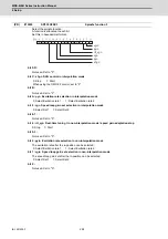
bit 4 : fdir Position feedback
Set the machine side encoder's installation polarity.
0: Forward polarity 1: Reverse polarity
bit 3 : vfb Speed feedback filter
0: Disable 1: Enable (4500Hz)
bit 2 : seqh READY ON sequence
0: Normal 1: High-speed
bit 1 : dfbx Dual feedback control
Control the position FB signal in full closed control by the combination of a motor side encoder and machine
side encoder.
0: Stop 1: Start
Related parameters: SP051, SP052
bit 0 : fdir2 Speed feedback polarity
Set the motor side encoder's installation polarity by a built-in motor.
0: Forward polarity 1: Reverse polarity
#13015
SP015 PY2
Minimum excitation rate 2
#13016
SP016 DDT
Phase alignment deceleration rate
(PR)
#13017
SP017 SPEC1
Spindle specification 1
msr
fdir
vfb
seqh
fdir2
dfbx
Summary of Contents for MDS-E
Page 1: ......
Page 3: ......
Page 15: ......
Page 17: ......
Page 19: ......
Page 21: ......
Page 31: ......
Page 32: ...1 IB 1501229 F 1 Installation ...
Page 76: ...45 IB 1501229 F 2 Wiring and Connection ...
Page 132: ...101 IB 1501229 F 3 Safety Function ...
Page 142: ...111 IB 1501229 F 4 Setup ...
Page 277: ...MDS E EH Series Instruction Manual 4 Setup 246 IB 1501229 F ...
Page 278: ...247 IB 1501229 F 5 Servo Adjustment ...
Page 351: ...MDS E EH Series Instruction Manual 5 Servo Adjustment 320 IB 1501229 F ...
Page 352: ...321 IB 1501229 F 6 Spindle Adjustment ...
Page 404: ...373 IB 1501229 F 7 Troubleshooting ...
Page 455: ...MDS E EH Series Instruction Manual 7 Troubleshooting 424 IB 1501229 F ...
Page 456: ...425 IB 1501229 F 8 Maintenance ...
Page 475: ...MDS E EH Series Instruction Manual 8 Maintenance 444 IB 1501229 F ...
Page 476: ...445 IB 1501229 F 9 Power Backup System ...
Page 494: ...463 IB 1501229 F 10 Appx 1 Cable and Connector Assembly ...
Page 504: ...473 IB 1501229 F 11 Appx 2 D A Output Specifications for Drive Unit ...
Page 514: ...483 IB 1501229 F 12 Appx 3 Protection Function ...
Page 523: ...MDS E EH Series Instruction Manual 12 Appx 3 Protection Function 492 IB 1501229 F ...
Page 524: ...493 IB 1501229 F 13 Appx 4 Compliance to EC Directives ...
Page 528: ...497 IB 1501229 F 14 Appx 5 EMC Installation Guidelines ...
Page 540: ...509 IB 1501229 F 15 Appx 6 Higher Harmonic Suppression Measure Guidelines ...
Page 550: ......
Page 554: ......

