MDS-E/EH Series Instruction Manual
4 Setup
227
IB-1501229-F
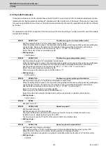
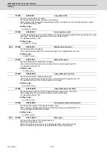
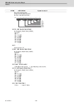
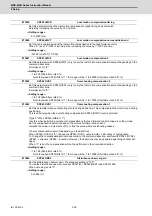
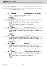
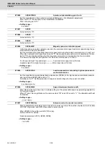
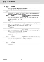
Set the disturbance observer filter band.
Normally, set to "100".
To use the disturbance observer, also set SP037(JL), SP044(OBS2) and SP226/ bitE.
When not using, set to "0".
---Setting range---
0 to 1000 (rad/s)
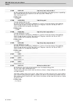
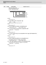
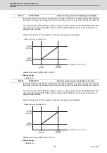
Set the vibration frequency to suppress when machine vibration occurs.
(Enabled at 50 or more.)
When not using, set to "0".
Related parameters: SP034/bit7-5
---Setting range---
0 to 5000 (Hz)
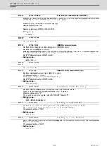
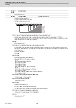
Set the inductive voltage compensation gain. Normally, set to "100".
Lower the gain when the current FB peak exceeds the current command peak.
---Setting range---
0 to 200 (%)
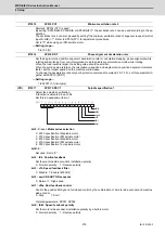
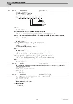
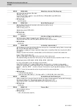
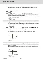
Set this parameter when the protrusion (that occurs due to the non-sensitive band by friction, torsion, back-
lash, etc.) at quadrant change is too large.
This sets the compensation torque at quadrant change (when an axis feed direction is reversed) by Short-
time rated %.
Whether to enable the lost motion compensation and the method can be set with other parameters.
[Type 2 "When SP033/bit9,8=10"]
Set the compensation amount based on the motor short-time rated current.
The standard setting is double of the friction torque. The compensation amount will be 0 when "0" is set.
Related parameters: SP033/bit9-8, SP039, SP040, SP041, SP227/bit2
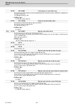
[To vary compensation amount depending on the direction]
When SP041 (LMC2) is "0", change SP048 (LMC1) value in both of +/- directions to compensate.
To vary the compensation amount depending on the command direction, set this with SP041 (LMC2).
(SP048: + direction, SP041: - direction, However, the directions may be opposite depending on other set-
tings.)
When "-1" is set, the compensation will not be performed in the command direction.
---Setting range---
-1 to 200 (Short-time rated %)
Note that when SP227/bit2 is "1", the range will be -1 to 20000 (Short-time rated 0.01%).
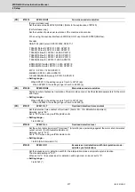
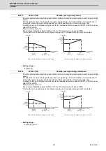
When a relative error in the synchronous control is too large, set this parameter to the axis that is delaying.
The standard setting is "0". The standard setting in the SHG control is "50".
Adjust relative errors in acceleration/deceleration by increasing the value by 50.
---Setting range---
0 to 999 (%)
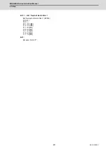
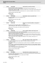
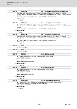
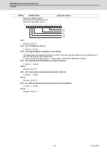
Set the imbalance torque.
---Setting range---
-100 to 100 (Short-time rated %)
#13045
SP045 OBS1
Disturbance observer filter frequency
#13046
SP046 FHz2
Notch filter frequency 2
#13047
SP047 EC
Inductive voltage compensation gain
#13048
SP048 LMC1
Lost motion compensation 1
#13049
SP049 FFC
Acceleration rate feed forward gain
#13050
SP050 TOF
Torque offset
Summary of Contents for MDS-E
Page 1: ......
Page 3: ......
Page 15: ......
Page 17: ......
Page 19: ......
Page 21: ......
Page 31: ......
Page 32: ...1 IB 1501229 F 1 Installation ...
Page 76: ...45 IB 1501229 F 2 Wiring and Connection ...
Page 132: ...101 IB 1501229 F 3 Safety Function ...
Page 142: ...111 IB 1501229 F 4 Setup ...
Page 277: ...MDS E EH Series Instruction Manual 4 Setup 246 IB 1501229 F ...
Page 278: ...247 IB 1501229 F 5 Servo Adjustment ...
Page 351: ...MDS E EH Series Instruction Manual 5 Servo Adjustment 320 IB 1501229 F ...
Page 352: ...321 IB 1501229 F 6 Spindle Adjustment ...
Page 404: ...373 IB 1501229 F 7 Troubleshooting ...
Page 455: ...MDS E EH Series Instruction Manual 7 Troubleshooting 424 IB 1501229 F ...
Page 456: ...425 IB 1501229 F 8 Maintenance ...
Page 475: ...MDS E EH Series Instruction Manual 8 Maintenance 444 IB 1501229 F ...
Page 476: ...445 IB 1501229 F 9 Power Backup System ...
Page 494: ...463 IB 1501229 F 10 Appx 1 Cable and Connector Assembly ...
Page 504: ...473 IB 1501229 F 11 Appx 2 D A Output Specifications for Drive Unit ...
Page 514: ...483 IB 1501229 F 12 Appx 3 Protection Function ...
Page 523: ...MDS E EH Series Instruction Manual 12 Appx 3 Protection Function 492 IB 1501229 F ...
Page 524: ...493 IB 1501229 F 13 Appx 4 Compliance to EC Directives ...
Page 528: ...497 IB 1501229 F 14 Appx 5 EMC Installation Guidelines ...
Page 540: ...509 IB 1501229 F 15 Appx 6 Higher Harmonic Suppression Measure Guidelines ...
Page 550: ......
Page 554: ......

