


Outline for MDS-E/EH Series
Specifications Manual
(IB-1501226-G)
1 Introduction
1.1 Servo/Spindle Drive System Configuration
1.1.1 System Configuration
1.2 Explanation of Type
1.2.1 Servo Motor Type
1.2.2 Servo Drive Unit Type
1.2.3 Spindle Motor Type
1.2.4 Tool Spindle Motor Type
1.2.5 Spindle Drive Unit Type
1.2.6 Power Supply Unit Type
1.2.7 AC Reactor Type
2 Specifications
2.1 Servo Motor
2.1.1 Specifications List
2.1.2 Torque Characteristics
2.2 Spindle Motor
2.2.1 Specifications
2.2.2 Output Characteristics
2.3 Tool Spindle Motor
2.3.1 Specifications
2.3.2 Output Characteristics
2.4 Drive Unit
2.4.1 Installation Environment Conditions
2.4.2 Servo Drive Unit
2.4.3 Spindle Drive Unit
2.4.4 Power Supply Unit
2.4.5 Unit Outline Dimension Drawing
2.4.6 AC Reactor
2.4.7 Explanation of Each Part
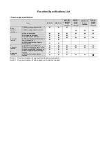
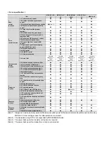
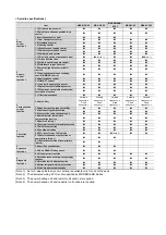
3 Function Specifications
Function Specifications List
3.1 Base Control Functions
3.1.1 Full Closed Loop Control
3.1.2 Position Command Synchronous Control
3.1.3 Speed Command Synchronous Control
3.1.4 Distance-coded Reference Position Control
3.1.5 Spindle's Continuous Position Loop Control
3.1.6 Coil Changeover Control
3.1.7 Gear Changeover Control
3.1.8 Orientation Control
3.1.9 Indexing Control
3.1.10 Synchronous Tapping Control
3.1.11 Spindle Synchronous Control
3.1.12 Spindle/C Axis Control
3.1.13 Proximity Switch Orientation Control
3.1.14 Power Regeneration Control
3.1.15 Resistor Regeneration Control
3.2 Servo/Spindle Control Functions
3.2.1 Torque Limit Function
3.2.2 Variable Speed Loop Gain Control
3.2.3 Gain Changeover for Synchronous Tapping Con-
trol
3.2.4 Speed Loop PID Changeover Control
3.2.5 Disturbance Torque Observer
3.2.6 Smooth High Gain Control (SHG Control)
3.2.7 High-speed Synchronous Tapping Control (OMR-
DD Control)
3.2.8 Dual Feedback Control
3.2.9 HAS Control
3.2.10 OMR-FF Control
3.2.11 Control Loop Gain Changeover
3.2.12 Spindle Output Stabilizing Control
3.2.13 High-response Spindle Acceleration/Decelera-
tion Function
3.3 Compensation Control Function
3.3.1 Jitter Compensation
3.3.2 Notch Filter
3.3.3 Adaptive Tracking-type Notch Filter
3.3.4 Overshooting Compensation
3.3.5 Machine End Compensation Control
3.3.6 Lost Motion Compensation Type 2
3.3.7 Lost Motion Compensation Type 3
3.3.8 Spindle Motor Temperature Compensation Func-
tion
3.3.9 Real-time Tuning I
3.3.10 Full-closed Torsion Compensation Function
3.4 Protection Function
3.4.1 Deceleration Control at Emergency Stop
3.4.2 Vertical Axis Drop Prevention/Pull-up Control
3.4.3 Earth Fault Detection
3.4.4 Collision Detection Function
3.4.5 Fan Stop Detection
3.4.6 Open-phase Detection
3.4.7 Contactor Weld Detection
3.4.8 STO (Safe Torque Off) Function
3.4.9 SBC (Safe Brake Control) Function
3.4.10 Deceleration and Stop Function at Power Fail-
ure
3.4.11 Retraction Function at Power Failure
3.5 Sequence Functions
3.5.1 Contactor Control Function
3.5.2 Motor Brake Control Function
3.5.3 External Emergency Stop Function
3.5.4 Specified Speed Output
3.5.5 Quick READY ON Sequence
3.6 Diagnosis Function
3.6.1 Monitor Output Function
3.6.2 Machine Resonance Frequency Display Function
3.6.3 Machine Inertia Display Function
3.6.4 Motor Temperature Display Function
3.6.5 Load Monitor Output Function
3.6.6 Power Supply Diagnosis Display Function
3.6.7 Drive Unit Diagnosis Display Function
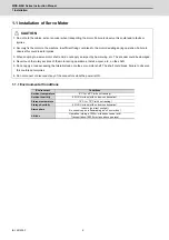
4 Characteristics
4.1 Servo Motor
4.1.1 Environmental Conditions
4.1.2 Quakeproof Level
4.1.3 Shaft Characteristics
4.1.4 Machine Accuracy
4.1.5 Oil/Water Standards
4.1.6 Installation of Servo Motor
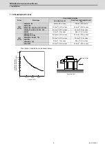
4.1.7 Overload Protection Characteristics
4.1.8 Magnetic Brake
4.1.9 Dynamic Brake Characteristics
4.2 Spindle Motor
4.2.1 Environmental Conditions
4.2.2 Shaft Characteristics
4.2.3 Machine Accuracy
4.2.4 Installation of Spindle Motor
4.3 Tool Spindle Motor
4.3.1 Environmental Conditions
4.3.2 Shaft Characteristics
4.3.3 Tool Spindle Temperature Characteristics
Summary of Contents for MDS-E
Page 1: ......
Page 3: ......
Page 15: ......
Page 17: ......
Page 19: ......
Page 21: ......
Page 31: ......
Page 32: ...1 IB 1501229 F 1 Installation ...
Page 76: ...45 IB 1501229 F 2 Wiring and Connection ...
Page 132: ...101 IB 1501229 F 3 Safety Function ...
Page 142: ...111 IB 1501229 F 4 Setup ...
Page 277: ...MDS E EH Series Instruction Manual 4 Setup 246 IB 1501229 F ...
Page 278: ...247 IB 1501229 F 5 Servo Adjustment ...
Page 351: ...MDS E EH Series Instruction Manual 5 Servo Adjustment 320 IB 1501229 F ...
Page 352: ...321 IB 1501229 F 6 Spindle Adjustment ...
Page 404: ...373 IB 1501229 F 7 Troubleshooting ...
Page 455: ...MDS E EH Series Instruction Manual 7 Troubleshooting 424 IB 1501229 F ...
Page 456: ...425 IB 1501229 F 8 Maintenance ...
Page 475: ...MDS E EH Series Instruction Manual 8 Maintenance 444 IB 1501229 F ...
Page 476: ...445 IB 1501229 F 9 Power Backup System ...
Page 494: ...463 IB 1501229 F 10 Appx 1 Cable and Connector Assembly ...
Page 504: ...473 IB 1501229 F 11 Appx 2 D A Output Specifications for Drive Unit ...
Page 514: ...483 IB 1501229 F 12 Appx 3 Protection Function ...
Page 523: ...MDS E EH Series Instruction Manual 12 Appx 3 Protection Function 492 IB 1501229 F ...
Page 524: ...493 IB 1501229 F 13 Appx 4 Compliance to EC Directives ...
Page 528: ...497 IB 1501229 F 14 Appx 5 EMC Installation Guidelines ...
Page 540: ...509 IB 1501229 F 15 Appx 6 Higher Harmonic Suppression Measure Guidelines ...
Page 550: ......
Page 554: ......


