

MDS-E/EH Series Instruction Manual
4 Setup
231
IB-1501229-F
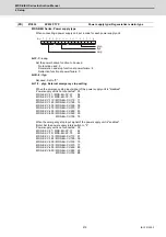
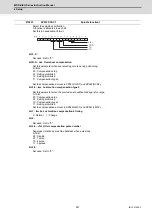
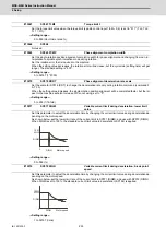
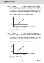
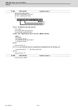
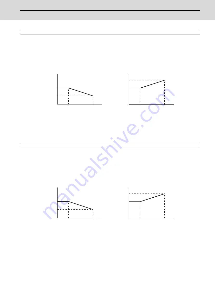
If noise is bothersome during high speed rotation, it may be reduced by lowering the speed loop gain at high
speed.
Set this value to ensure the adequate response by suppressing noise and vibration at low speeds and in-
creasing the speed loop gain at high speeds for a high-speed spindle of machining center, etc.
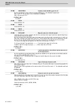
As shown below, set the speed loop gain rate for the overspeed detection speed in SP073 (VGVN), and use
with SP074 (VGVS).
When not using, set to "0".
The overspeed detection speed (VLMT) is 115% of the maximum motor speed (TSP).
This function can be used when either Speed loop gain set 1 or Speed loop gain set 2 is selected.
---Setting range---
0 to 999 (%)
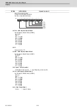
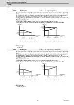
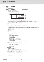
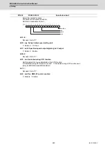
If noise is bothersome during high speed rotation, it may be reduced by lowering the speed loop gain at high
speed.
Set this value to ensure the adequate response by suppressing noise and vibration at low speeds and in-
creasing the speed loop gain at high speeds for a high-speed spindle of machining center, etc.
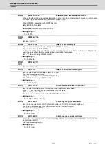
As shown below, set the speed loop gain rate for the overspeed detection speed in SP073 (VGVN), and use
with SP074 (VGVS).
When not using, set to "0".
The overspeed detection speed (VLMT) is 115% of the maximum motor speed (TSP).
This function can be used when either Speed loop gain set 1 or Speed loop gain set 2 is selected.
---Setting range---
0 to 32767 (r/min)
#13073
SP073 VGVN
Variable speed gain target value
#13074
SP074 VGVS
Variable speed gain change start speed
VGVN
(SP073)
<100
VGVS
(SP074)
VLMT
(SP026x1.15)
100
VGVN
(SP073)
>100
VGVS
(SP074)
VLMT
(SP026x1.15)
100
Scale[%]
Scale[%]
Motor speed
[r/min]
When lowering the speed loop gain at high speed
When increasing the speed loop gain at high speed
Motor speed
[r/min]
VGVN
(SP073)
<100
VGVS
(SP074)
VLMT
(SP026x1.15)
100
VGVN
(SP073)
>100
VGVS
(SP074)
VLMT
(SP026x1.15)
100
Scale[%]
Scale[%]
Motor speed
[r/min]
When lowering the speed loop gain at high speed
When increasing the speed loop gain at high speed
Motor speed
[r/min]
Summary of Contents for MDS-E
Page 1: ......
Page 3: ......
Page 15: ......
Page 17: ......
Page 19: ......
Page 21: ......
Page 31: ......
Page 32: ...1 IB 1501229 F 1 Installation ...
Page 76: ...45 IB 1501229 F 2 Wiring and Connection ...
Page 132: ...101 IB 1501229 F 3 Safety Function ...
Page 142: ...111 IB 1501229 F 4 Setup ...
Page 277: ...MDS E EH Series Instruction Manual 4 Setup 246 IB 1501229 F ...
Page 278: ...247 IB 1501229 F 5 Servo Adjustment ...
Page 351: ...MDS E EH Series Instruction Manual 5 Servo Adjustment 320 IB 1501229 F ...
Page 352: ...321 IB 1501229 F 6 Spindle Adjustment ...
Page 404: ...373 IB 1501229 F 7 Troubleshooting ...
Page 455: ...MDS E EH Series Instruction Manual 7 Troubleshooting 424 IB 1501229 F ...
Page 456: ...425 IB 1501229 F 8 Maintenance ...
Page 475: ...MDS E EH Series Instruction Manual 8 Maintenance 444 IB 1501229 F ...
Page 476: ...445 IB 1501229 F 9 Power Backup System ...
Page 494: ...463 IB 1501229 F 10 Appx 1 Cable and Connector Assembly ...
Page 504: ...473 IB 1501229 F 11 Appx 2 D A Output Specifications for Drive Unit ...
Page 514: ...483 IB 1501229 F 12 Appx 3 Protection Function ...
Page 523: ...MDS E EH Series Instruction Manual 12 Appx 3 Protection Function 492 IB 1501229 F ...
Page 524: ...493 IB 1501229 F 13 Appx 4 Compliance to EC Directives ...
Page 528: ...497 IB 1501229 F 14 Appx 5 EMC Installation Guidelines ...
Page 540: ...509 IB 1501229 F 15 Appx 6 Higher Harmonic Suppression Measure Guidelines ...
Page 550: ......
Page 554: ......


