MDS-E/EH Series Instruction Manual
4 Setup
237
IB-1501229-F
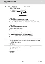
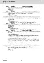
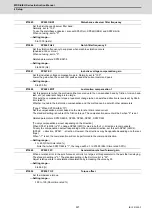
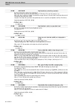
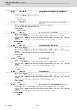
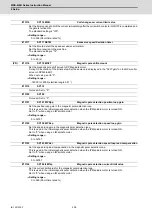
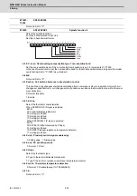
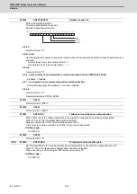
Input the desired data number to D/A output channel.
When using the 2-axis drive unit, set "-1" to the axis that the data will not be output.
When the DC excitation is running:
Use in the DC excitation function.
DC excitation: Set the initial excitation level when SP225/bit4=1.
When "0" is set, the state will be the same as when "20" is set.
---Setting range---
-32768 to 32767
Input the desired data number to D/A output channel.
When using the 2-axis drive unit, set "-1" to the axis that the data will not be output.
When the DC excitation is running:
Use in the DC excitation function.
DC excitation: Set the final excitation level when SP225/bit4=1.
When "0" is set, the state will be the same as when "50" is set.
---Setting range---
-32768 to 32767
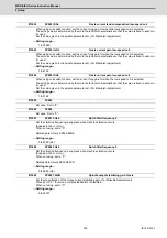
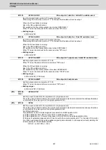
Set the output scale in increments of 1/100.
When "0" is set, the scale is the same as when "100" is set.
When the DC excitation is running:
Use in the DC excitation function.
DC excitation: Set the initial excitation time when SP225/bit4=1.
When "0" is set, the state will be the same as when "10000" is set.
---Setting range---
-32768 to 32767 (1/100-fold)
Set the output scale in increments of 1/100.
When "0" is set, the scale is the same as when "100" is set.
---Setting range---
-32768 to 32767 (1/100-fold)
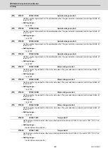
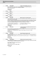
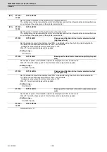
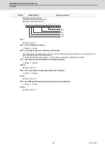
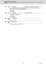
Set the unique constants for the spindle motor. (High-speed coil)
The setting value is determined by the motor's mechanical and electrical characteristics and specifications,
so normally set the value given in the spindle parameter list.
Set the unique constants for the spindle motor. (High-speed coil)
The setting value is determined by the motor's mechanical and electrical characteristics and specifications,
so normally set the value given in the spindle parameter list.
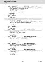
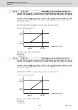
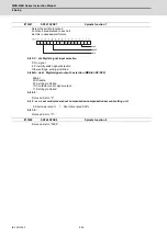
For IPM spindle motor
This parameter is used in initial magnetic pole detection of IPM spindle motor.
(1) Pulse application time: Set it in [
μ
s] unit.(0 < application time < 350)
(2) Pulse application coil: To select a low-speed coil, add 1000 to the pulse application time.
(3) Polarity of estimated magnetic pole: When it is set to the reverse polarity, add "-" to the total of (1) and (2).
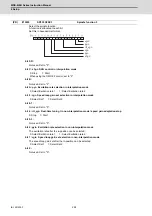
E.g.: When performing 333
μ
s pulse-applied magnetic pole estimation in a low-speed coil and selecting the
reverse polarity for the estimated polarity
SP142 = -(333+1000) = -1333
#13125
SP125 DA1NO
D/A output ch1 data No. / Initial DC excitation level
#13126
SP126 DA2NO
D/A output ch2 data No. / Final DC excitation level
#13127
SP127 DA1MPY
D/A output ch1 output scale / Initial DC excitation time
#13128
SP128 DA2MPY
D/A output ch2 output scale
(PR)
#13129-
13141
SP129-SP141
(PR)
#13142
SP142
Summary of Contents for MDS-E
Page 1: ......
Page 3: ......
Page 15: ......
Page 17: ......
Page 19: ......
Page 21: ......
Page 31: ......
Page 32: ...1 IB 1501229 F 1 Installation ...
Page 76: ...45 IB 1501229 F 2 Wiring and Connection ...
Page 132: ...101 IB 1501229 F 3 Safety Function ...
Page 142: ...111 IB 1501229 F 4 Setup ...
Page 277: ...MDS E EH Series Instruction Manual 4 Setup 246 IB 1501229 F ...
Page 278: ...247 IB 1501229 F 5 Servo Adjustment ...
Page 351: ...MDS E EH Series Instruction Manual 5 Servo Adjustment 320 IB 1501229 F ...
Page 352: ...321 IB 1501229 F 6 Spindle Adjustment ...
Page 404: ...373 IB 1501229 F 7 Troubleshooting ...
Page 455: ...MDS E EH Series Instruction Manual 7 Troubleshooting 424 IB 1501229 F ...
Page 456: ...425 IB 1501229 F 8 Maintenance ...
Page 475: ...MDS E EH Series Instruction Manual 8 Maintenance 444 IB 1501229 F ...
Page 476: ...445 IB 1501229 F 9 Power Backup System ...
Page 494: ...463 IB 1501229 F 10 Appx 1 Cable and Connector Assembly ...
Page 504: ...473 IB 1501229 F 11 Appx 2 D A Output Specifications for Drive Unit ...
Page 514: ...483 IB 1501229 F 12 Appx 3 Protection Function ...
Page 523: ...MDS E EH Series Instruction Manual 12 Appx 3 Protection Function 492 IB 1501229 F ...
Page 524: ...493 IB 1501229 F 13 Appx 4 Compliance to EC Directives ...
Page 528: ...497 IB 1501229 F 14 Appx 5 EMC Installation Guidelines ...
Page 540: ...509 IB 1501229 F 15 Appx 6 Higher Harmonic Suppression Measure Guidelines ...
Page 550: ......
Page 554: ......

